
Variable Resistance
Thermistors
- A thermistor is a non-ohmic conductor and sensory resistor whose resistance varies with temperature
- Most thermistors are negative temperature coefficient (ntc) components.
- This means that if the temperature increases, the resistance of the thermistor decreases (and vice versa)
- The temperature-resistance graph for a thermistor is shown below
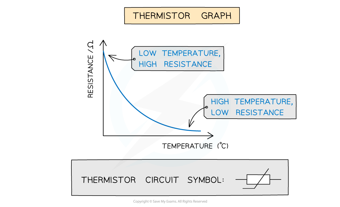
Graph of temperature against resistance for a thermistor
- Thermistors are temperature sensors and are used in circuits in ovens, fire alarms and digital thermometers
- As the thermistor gets hotter, its resistance decreases
- As the thermistor gets cooler, its resistance increases
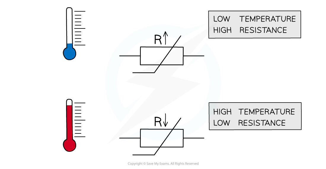
The resistance through a thermistor is dependent on the temperature of it
Light-dependent resistors (LDR)
- A light-dependent resistor (LDR) is a non-ohmic conductor and sensory resistor
- Its resistance automatically changes depending on the light energy falling onto it (illumination)
- This is shown by the following graph:
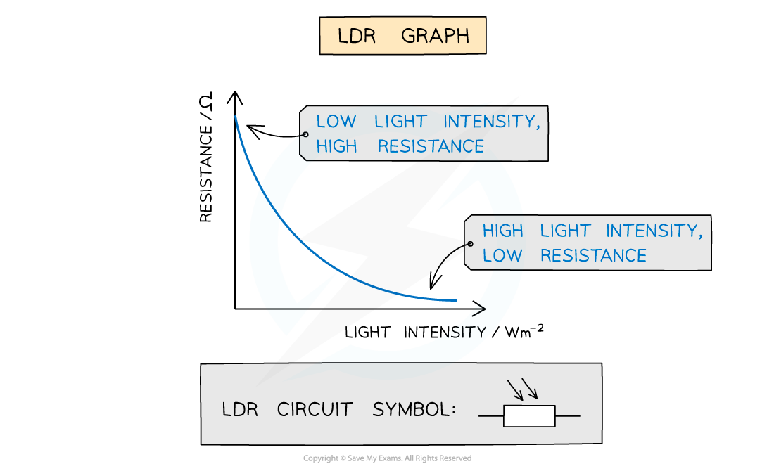
Graph of light intensity and resistance for an LDR
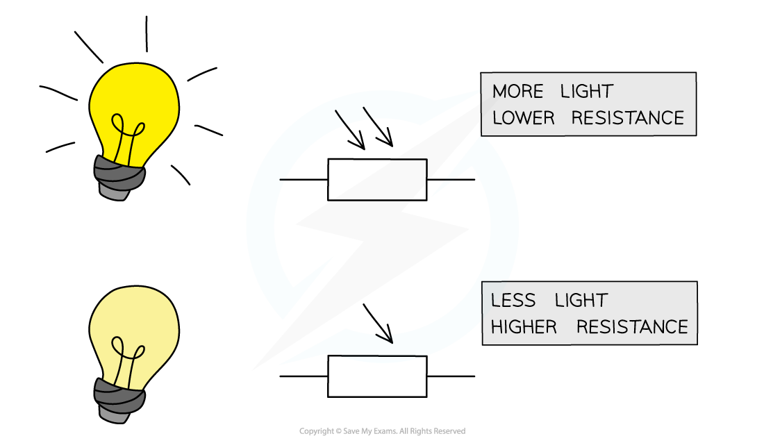
- As the light intensity increases, the resistance of an LDR decreases
Resistance of an LDR depends on the light intensity falling on it
- LDRs can be used as light sensors, so, they are useful in circuits which automatically switch on lights when it gets dark, for example, street lighting and garden lights
- In the dark, its resistance is very large (millions of ohms)
- In bright light, its resistance is small (tens of ohms)
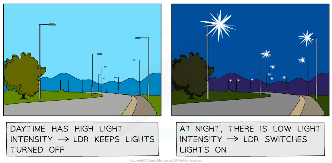
LDRs are used for automatic street lights
Potentiometer
- A potentiometer is similar to a variable resistor connected as a potential divider to give a continuously variable output voltage
- It can be used as a means of comparing potential differences in different parts of the circuit
- It is recognised on a circuit diagram with a resistor fitted with a sliding contact
- The sliding contact has the effect of separating the potentiometer into two parts (an upper part and a lower part), both of which have different resistances

Moving the slider (the arrow in the diagram) changes the resistance (and hence potential difference) of the upper and lower parts of the potentiometer
- If the slider in the above diagram is moved upwards, the resistance of the lower part will increase and so the potential difference across it will also increase
- Therefore, the variable resistor obtains a maximum or minimum value for the output voltage
- If the resistance is 3 Ω:
- Maximum voltage is when the resistance is 3 Ω
- Minimum voltage is when the resistance is 0 Ω
Worked example
A thermistor is connected in series with a resistor R and a battery.

The resistance of the thermistor is equal to the resistance of R at room temperature. When the temperature of the thermistor decreases, which statement is correct?
A. The p.d across the thermistor increases
B. The current in R increases
C. The current through the thermistor decreases
D. The p.d across R increases
ANSWER: A
- The resistance of the thermistor increases as the temperature decreases
- Since the thermistor and resistor R are connected in series, the current I in both of them is the same
- Ohm’s law states that V = IR
- Since the resistance of the thermistor increases, and I is the same, the potential difference V across it increases
- Therefore, statement A is correct
Worked example
Which graph best represents the way in which the current I through an LDR depends upon the potential difference V across it?
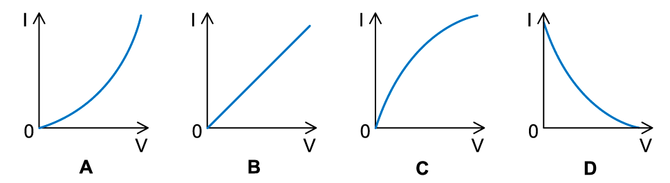
ANSWER: B
- As the potential difference across the LDR increases, the light intensity increases causing its resistance to decrease
- Ohm’s law states that V = IR
- The resistance is equal to V/I or 1/R = I/V = gradient of the graph
- Since R decreases, the value of 1/R increases, so the gradient must increase
- Therefore, I increases with the p.d with an increasing gradient
