Lenz's Law
- Lenz’s Law is used to predict the direction of an induced e.m.f in a coil or wire
- It is a consequence of the principle of conservation of energy
- Lenz's Law is summarised below:
The induced e.m.f is such that it will oppose the change causing it
- Lenz’s law combined with Faraday’s law is given by the equation:
format('truetype')%3Bfont-weight%3Anormal%3Bfont-style%3Anormal%3B%7D%3C%2Fstyle%3E%3C%2Fdefs%3E%3Ctext%20font-family%3D%22Times%20New%20Roman%22%20font-size%3D%2218%22%20font-style%3D%22italic%22%20text-anchor%3D%22middle%22%20x%3D%224.5%22%20y%3D%2230%22%3E%26%23x3B5%3B%3C%2Ftext%3E%3Ctext%20font-family%3D%22math196650bafcbad352c1b3bb8d293%22%20font-size%3D%2216%22%20text-anchor%3D%22middle%22%20x%3D%2221.5%22%20y%3D%2230%22%3E%3D%3C%2Ftext%3E%3Ctext%20font-family%3D%22math196650bafcbad352c1b3bb8d293%22%20font-size%3D%2216%22%20font-style%3D%22italic%22%20text-anchor%3D%22middle%22%20x%3D%2242.5%22%20y%3D%2230%22%3E%26%23x2212%3B%3C%2Ftext%3E%3Ctext%20font-family%3D%22Times%20New%20Roman%22%20font-size%3D%2218%22%20font-style%3D%22italic%22%20text-anchor%3D%22middle%22%20x%3D%2257.5%22%20y%3D%2230%22%3EN%3C%2Ftext%3E%3Cline%20stroke%3D%22%23000000%22%20stroke-linecap%3D%22square%22%20stroke-width%3D%221%22%20x1%3D%2267.5%22%20x2%3D%2299.5%22%20y1%3D%2223.5%22%20y2%3D%2223.5%22%2F%3E%3Ctext%20font-family%3D%22math196650bafcbad352c1b3bb8d293%22%20font-size%3D%2216%22%20text-anchor%3D%22middle%22%20x%3D%2276.5%22%20y%3D%2216%22%3E%26%23x2206%3B%3C%2Ftext%3E%3Ctext%20font-family%3D%22Times%20New%20Roman%22%20font-size%3D%2218%22%20font-style%3D%22italic%22%20text-anchor%3D%22middle%22%20x%3D%2290.5%22%20y%3D%2216%22%3E%26%23x3A6%3B%3C%2Ftext%3E%3Ctext%20font-family%3D%22math196650bafcbad352c1b3bb8d293%22%20font-size%3D%2216%22%20text-anchor%3D%22middle%22%20x%3D%2280.5%22%20y%3D%2241%22%3E%26%23x2206%3B%3C%2Ftext%3E%3Ctext%20font-family%3D%22Times%20New%20Roman%22%20font-size%3D%2218%22%20font-style%3D%22italic%22%20text-anchor%3D%22middle%22%20x%3D%2290.5%22%20y%3D%2241%22%3Et%3C%2Ftext%3E%3C%2Fsvg%3E)
- This equation shows:
- When a bar magnet goes through a coil, an e.m.f is induced within the coil due to a change in magnetic flux
- A current is also induced which means the coil now has its own magnetic field
- The coil’s magnetic field acts in the opposite direction to the magnetic field of the bar magnet (shown by the minus sign)
- If a direct current (d.c) power supply is replaced with an alternating current (a.c) supply, the e.m.f induced will also be alternating with the same frequency as the supply
Experimental Evidence for Lenz’s Law
- To verify Lenz’s Law, the only apparatus needed is:
- A bar magnet
- A coil of wire
- A sensitive ammeter
- Note: a cell is not required
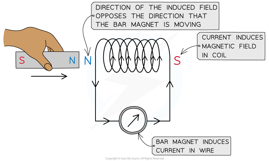
Lenz’s law can be verified using a coil connected in series with a sensitive ammeter and a bar magnet
- A known pole (either north or south) of a bar magnet is pushed into the coil
- This induces an e.m.f in the coil
- The induced e.m.f drives a current (because it is a complete circuit)
- Lenz's Law dictates:
- The direction of the e.m.f, and hence the current, must be set up to oppose the incoming magnet
- Since a north pole approaches the coil face, the e.m.f must be set up to create an induced north pole
- This is because the two north poles will repel each other
- The direction of the current is therefore as shown in the image above
- The direction of the current can be verified using the right-hand grip rule
- Fingers curl around the coil in the direction of current and the thumb points along the direction of the flux lines, from north to south
- Therefore, the current flows in an anti-clockwise direction in the image shown, in order to induce a north pole opposing the incoming magnet

- Reversing the magnet direction would give an opposite deflection on the voltmeter
- Lenz's Law would then predict a south pole induced at the coil entrance (next to the bar magnet)
- This would create a north pole at the exist, attracting the bar's south pole attempting to leave
- Therefore, the induced e.m.f always produces effects to oppose the changes causing it
- This means:
- The coil will try and push the bar magnet to stop it from entering
- The coil will try and pull the bar magnet to stop it from leaving
- This means the poles of the coil swaps around as the bar magnet travels through
- Lenz's Law is a direct consequence of the principle of conservation of energy
- Electromagnetic effects will not create electrical energy out of nothing
- In order to induce and sustain an e.m.f, for instance, work must be done in order to overcome the repulsive effect due to Lenz's Law
Worked example
Two conducting loops, X and Y, are positioned so that their planes are parallel and their centres sit on the same line, as shown in the diagram.

When the switch S is closed, a constant counterclockwise current flows in X. Loop X is stationary and loop Y is moved towards X at a constant speed.
State and explain:
Work must be done on loop Y to maintain its constant speed towards X
Answer:
(a) Variation of magnetic flux in Y:
- As Y approaches X, it cuts an increasing number of magnetic field lines
- Therefore, the magnetic flux in Y increases as it approaches X

(b) Direction of the induced current in Y:
- Lenz's law states that the induced e.m.f will be such that it will oppose the change producing it
- Hence, the induced current in Y will flow in a constant clockwise direction

Size of the induced current in Y:
- Faraday's law states that the induced e.m.f. increases with the rate of change of flux linkage
- The rate of change of magnetic flux in Y increases as it approaches X
- Potential difference and current are related by
format('truetype')%3Bfont-weight%3Anormal%3Bfont-style%3Anormal%3B%7D%3C%2Fstyle%3E%3C%2Fdefs%3E%3Ctext%20font-family%3D%22Times%20New%20Roman%22%20font-size%3D%2218%22%20font-style%3D%22italic%22%20text-anchor%3D%22middle%22%20x%3D%226.5%22%20y%3D%2216%22%3EV%3C%2Ftext%3E%3Ctext%20font-family%3D%22math17f39f8317fbdb1988ef4c628eb%22%20font-size%3D%2216%22%20text-anchor%3D%22middle%22%20x%3D%2226.5%22%20y%3D%2216%22%3E%3D%3C%2Ftext%3E%3Ctext%20font-family%3D%22Times%20New%20Roman%22%20font-size%3D%2218%22%20font-style%3D%22italic%22%20text-anchor%3D%22middle%22%20x%3D%2242.5%22%20y%3D%2216%22%3EI%3C%2Ftext%3E%3Ctext%20font-family%3D%22Times%20New%20Roman%22%20font-size%3D%2218%22%20font-style%3D%22italic%22%20text-anchor%3D%22middle%22%20x%3D%2251.5%22%20y%3D%2216%22%3ER%3C%2Ftext%3E%3C%2Fsvg%3E)
- The resistance of the loop is constant, hence, the size of the induced current in Y will increase with time
(c) Why work must be done to maintain a constant speed:
- The current induced in Y produces a magnetic field opposing that of X
- So, according to Lenz's law, there will be a magnetic force opposing the motion of Y
- Hence, work must be done on Y to overcome this opposing force
Exam Tip
You should remember that the negative sign is representative of Lenz's Law (without out it, it is just Faraday's Law) which says that the induced e.m.f ε is set up to oppose the change causing it. The negative sign indicates motion in an opposing direction. This is the form of the equation given on your data booklet.

format('truetype')%3Bfont-weight%3Anormal%3Bfont-style%3Anormal%3B%7D%3C%2Fstyle%3E%3C%2Fdefs%3E%3Ctext%20font-family%3D%22math1262cc16475a9ecd4e5a750fee2%22%20font-size%3D%2216%22%20text-anchor%3D%22middle%22%20x%3D%228.5%22%20y%3D%2230%22%3E%26%23x221D%3B%3C%2Ftext%3E%3Ctext%20font-family%3D%22math1262cc16475a9ecd4e5a750fee2%22%20font-size%3D%2216%22%20text-anchor%3D%22middle%22%20x%3D%2228.5%22%20y%3D%2230%22%3E%26%23x2212%3B%3C%2Ftext%3E%3Cline%20stroke%3D%22%23000000%22%20stroke-linecap%3D%22square%22%20stroke-width%3D%221%22%20x1%3D%2239.5%22%20x2%3D%2264.5%22%20y1%3D%2223.5%22%20y2%3D%2223.5%22%2F%3E%3Ctext%20font-family%3D%22math1262cc16475a9ecd4e5a750fee2%22%20font-size%3D%2216%22%20text-anchor%3D%22middle%22%20x%3D%2248.5%22%20y%3D%2216%22%3E%26%23x2206%3B%3C%2Ftext%3E%3Ctext%20font-family%3D%22Times%20New%20Roman%22%20font-size%3D%2218%22%20font-style%3D%22italic%22%20text-anchor%3D%22middle%22%20x%3D%2259.5%22%20y%3D%2216%22%3EI%3C%2Ftext%3E%3Ctext%20font-family%3D%22math1262cc16475a9ecd4e5a750fee2%22%20font-size%3D%2216%22%20text-anchor%3D%22middle%22%20x%3D%2249.5%22%20y%3D%2241%22%3E%26%23x2206%3B%3C%2Ftext%3E%3Ctext%20font-family%3D%22Times%20New%20Roman%22%20font-size%3D%2218%22%20font-style%3D%22italic%22%20text-anchor%3D%22middle%22%20x%3D%2259.5%22%20y%3D%2241%22%3Et%3C%2Ftext%3E%3C%2Fsvg%3E)