Young’s Double-Slit Experiment (DP IB Physics): Revision Note
Young's Double Slit Experiment
Young's double-slit experiment produces a diffraction and an interference pattern using either:
The interference of two coherent wave sources
A single wave source passing through a double slit
Lasers are the most common sources used in Young's double slit experiment because the waves must be:
Coherent (have a constant phase difference and frequency)
Monochromatic (have the same wavelength)
In this typical set up for Young's double slit experiment:
The light source is placed behind the single slit
The light is then diffracted to produce two sources in the double slit at A and B
The light from the double slits is then diffracted, producing a diffraction pattern made up of bright and dark fringes on a screen
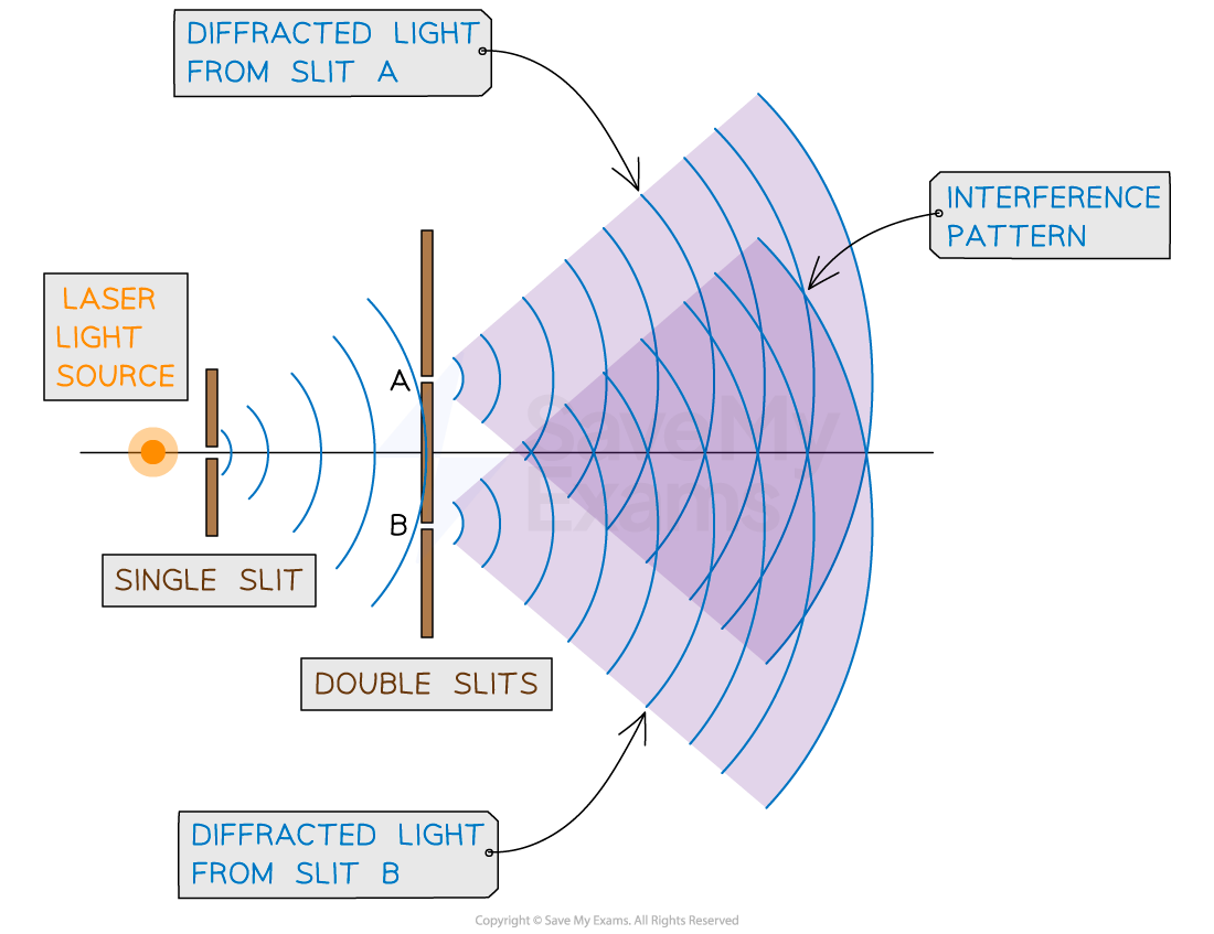
The typical arrangement of Young's double slit experiment
Diffraction Pattern
The diffraction pattern from the interference of the two sources can be seen on the screen when it is placed far away
Constructive interference between light rays forms bright strips, also called fringes, interference fringes or maxima, on the screen
Destructive interference forms dark strips, also called dark fringes or minima, on the screen
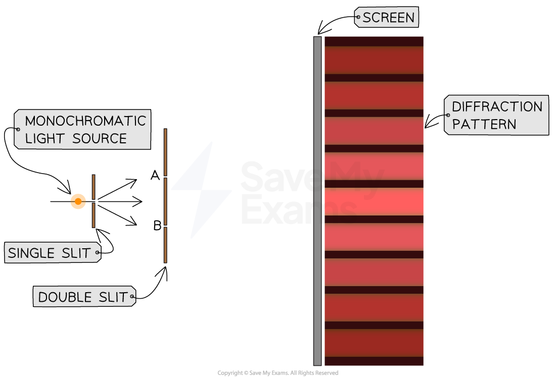
Young's double slit experiment and the resulting diffraction pattern
Each bright fringe is identical and has the same width and intensity
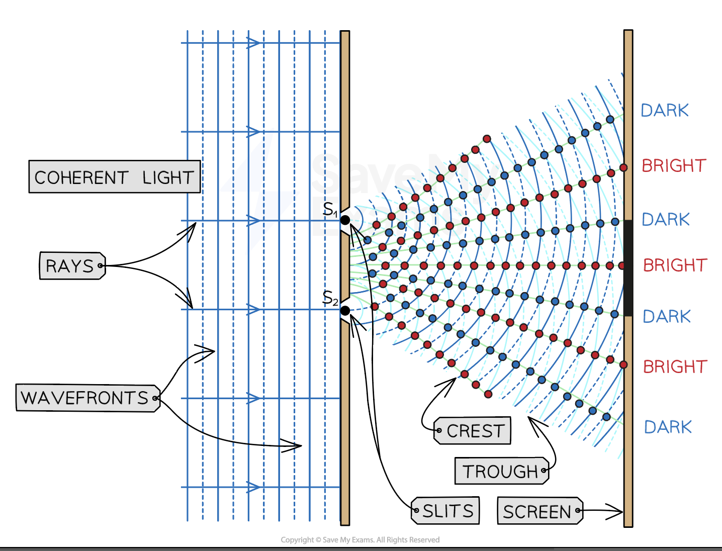
The constructive and destructive interference of laser light through a double slit creates bright and dark strips called fringes on a screen placed far away
Interference Pattern
The Young's double slit interference pattern shows the regions of constructive and destructive interference:
Each bright fringe is a peak of equal maximum intensity
Each dark fringe is a a trough or minimum of zero intensity
The maxima are formed by the constructive interference of light
The minima are formed by the destructive interference of light
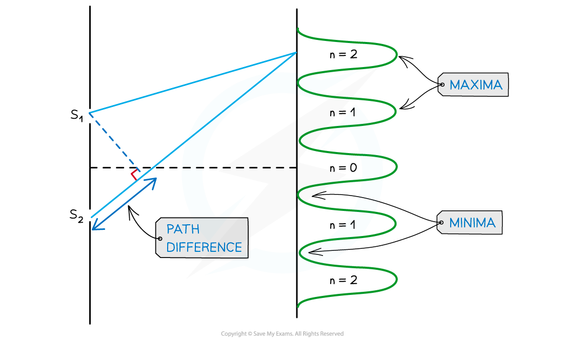
The interference pattern of Young's double slit diffraction of light
When two waves interfere, the resultant wave depends on the path difference between the two waves
The wave from slit S2 has to travel slightly further than that from S1 to reach the same point on the screen
This extra distance is the path difference
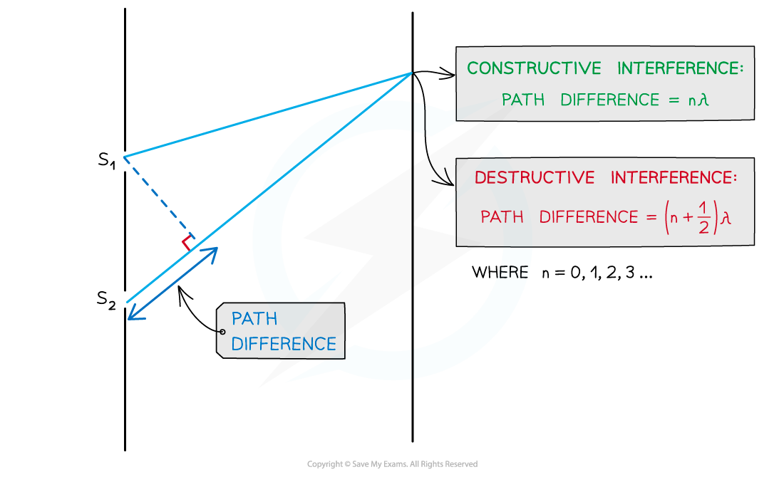
The path difference between two waves is determined by the number of wavelengths that cover their difference in length
Remember the conditions for interference as explained in the previous revision note on double source interference
For constructive interference (or maxima):
path difference =
For destructive interference (or minima):
path difference =
For the maxima in the interference pattern:
There is usually more than one produced
n is the order of the maxima or minima; which represents the position of the maxima away from the central maximum
n = 0 is the central maximum
n = 1 represents the first maximum on either side of the central, n = 2 the next one along....
Double Slit Equation
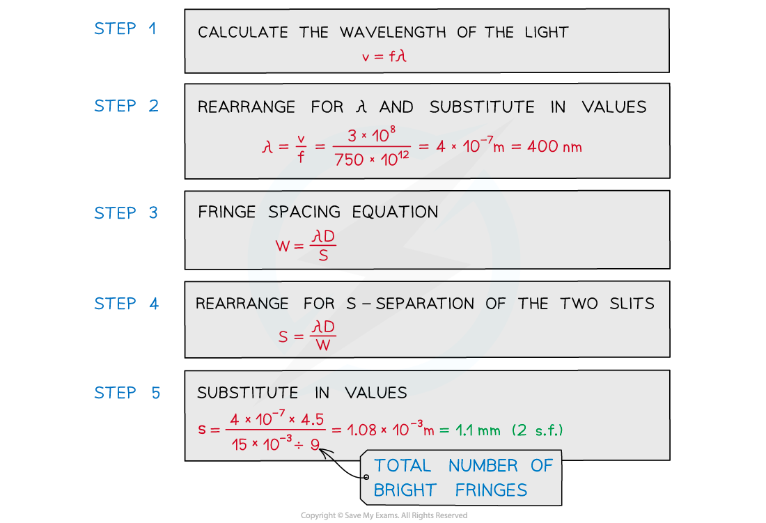
The spacing between the bright or dark fringes in the diffraction pattern formed on the screen can be calculated using the double-slit equation:
Where:
s = separation between successive fringes on the screen (m)
λ = wavelength of the waves incident on the slits (m)
D = distance between the screen and the slits (m)
d = separation between the slits (m)

Double slit interference equation with w, d and D represented on a diagram
The above equation shows that the separation between the fringes, s will increase if:
The wavelength of the incident light increases
The distance between the screen and the slits increases
The separation between the slits decreases
Worked Example
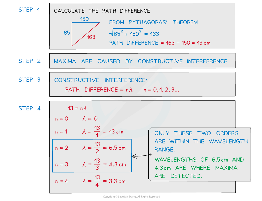
Two coherent sources of sound waves S1 and S2 are situated 65 cm apart in air as shown below.

The two sources vibrate in phase but have different amplitudes of vibration. A microphone M is situated 150 cm from S1 along the line normal to S1. The microphone detects maxima and minima of the intensity of the sound. The wavelength of the sound from S1 to S2 is decreased by increasing the frequency.
Determine which orders of maxima are detected at M as the wavelength is increased from 3.5 cm to 12.5 cm.
Answer:
Worked Example
A laser is placed in front of a double-slit as shown in the diagram below.
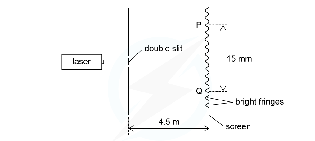
The laser emits light of frequency 750 THz. The separation of the maxima P and Q observed on the screen is 15 mm. The distance between the double slit and the screen is 4.5 m.
Calculate the separation of the two slits.
Answer:
Examiner Tips and Tricks
The path difference is more specifically how much longer, or shorter, one path is than the other. In other words, the difference in the distances. Make sure not to confuse this with the distance between the two paths.
Since d, s and D are all distances, it's easy to mix up which they refer to. Labelling the double-slit diagram as shown in the notes above will help to remember the order i.e. d and s in the numerator and D underneath in the denominator.

Unlock more, it's free!
Did this page help you?