IV Graphs (Edexcel IGCSE Physics (Modular)): Revision Note
Exam code: 4XPH1

IV graphs
When the voltage V across a component is varied, the current I flowing through it may vary linearly or non-linearly
The relationship between current and voltage of a component can be shown on an IV graph
When the relationship between current and voltage is linear:
the IV graph is a straight line which passes through the origin
the resistance is constant
When the relationship between current and voltage is non-linear:
the IV graph that is not a straight line
the resistance is not constant
Linear and non-linear IV graphs

Linear IV graphs are straight lines through the origin, indicating a constant resistance. Non-linear IV graphs are curved, indicating a variable resistance
Components with linear IV graphs include:
fixed resistors (at constant temperature)
wires (at constant temperature)
Components with non-linear IV graphs include:
filament lamps
diodes
LDRs
thermistors
IV graph for a wire or a resistor
The relationship between current and voltage for a wire or fixed resistor is linear, or directly proportional, which means
the IV graph is a straight line, so voltage and current increase (or decrease) by the same amount
the slope of the graph is constant, so resistance is constant

The current is directly proportional to the potential difference (voltage) as the graph is a straight line through the origin
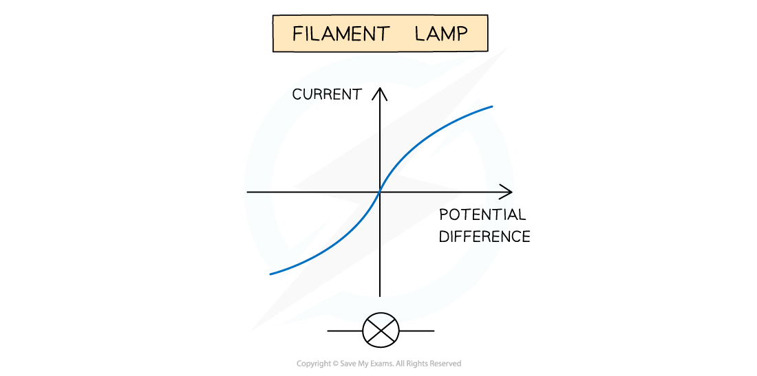
IV graph for a filament bulb
The relationship between current and voltage for a filament lamp is non-linear, or not directly proportional, which means
the IV graph is not a straight line, so voltage and current do not increase (or decrease) by the same amount
the slope of the graph is not constant, so resistance changes
The IV graph for a filament lamp shows as voltage increases
the current increases at a proportionally slower rate
the resistance increases; the flatter the slope, the higher the resistance
IV graph for a filament lamp
As current through a filament lamp increases, the resistance increases because:
the higher current causes the temperature of the filament to increase
the higher temperature causes the atoms in the metal lattice of the filament to vibrate more
this causes an increase in resistance as it becomes more difficult for free electrons (the current) to pass through
since resistance opposes the current, this causes it to increase at a slower rate
IV graph for a diode
A diode allows current to flow in one direction only
This is called forward bias
In the reverse direction, the diode has very high resistance, and therefore no current flows
This is called reverse bias
When the current is in the direction of the arrowhead symbol, this is forward bias
On the IV graph, this is shown by a sharp increase in voltage and current on the right side of the graph
This shows the resistance is very low
When the diode is switched around, this is reverse bias
On the IV graph, this is shown by a zero reading of current or voltage on the left side of the graph
This shows the resistance is very high

IV graph for a semiconductor diode
Investigating the relationship between current and voltage
In order to investigate the relationship between current and voltage different components, the following equipment is required:
an ammeter - to measure the current through the component
a voltmeter - to measure the voltage across the component
a variable resistor - to vary the current through the circuit
a power source - to provide a source of potential difference (voltage)
wires - to connect the components together in a circuit
The image below shows the circuits set up to obtain IV graphs for a filament lamp and a diode

These circuits enable the investigation of current and voltage for a filament lamp or diode to be investigated
The current is the independent variable
The variable resistor is used to change the current flowing through the filament lamp / diode
The voltage is the dependent variable
The voltmeter is used to measure the voltage across the filament lamp / diode
Recording measurements of current and voltage as the current increases enables an IV graph to be plotted for each component
Resistance
Resistance is the opposition to the flow of current
The higher the resistance of a circuit the lower the current
Resistors come in two types:
Fixed resistors
Variable resistors
Fixed resistors have a resistance that remains constant
Variable resistors can change the resistance by changing the length of wire that makes up the circuit
A longer length of wire has more resistance than a shorter length of wire

Fixed and variable resistor circuit symbols

Unlock more, it's free!
Join the 100,000+ Students that ❤️ Save My Exams
the (exam) results speak for themselves:

Was this revision note helpful?