Resistance (Cambridge (CIE) IGCSE Physics) : Revision Note

Did this video help you?
Ohm's law
Resistance
Resistance is defined as:
The opposition to current
Resistance occurs because the free electrons flowing in the circuit (current) collide with the metal ions in the wire
These collisions slow down the electrons, or, in other words, resist their flow
The higher the resistance of a circuit, the lower the current
This means that good conductors have a low resistance and insulators have a high resistance
The resistance of a circuit can be increased by adding resistors (or variable resistors) to it
Every electrical component has a resistance, even wires
In exam questions, the resistance of the wires and batteries are assumed to be negligible
The effect of resistance on the current in a circuit
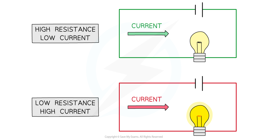
When a circuit has a high resistance, a lower current will flow, and vice versa
Ohm's law
Current,
 , potential difference,
  , and resistance,
  , all affect one another
Changing any one of these in a circuit, changes all of them
Current and resistance are inversely proportional
If the resistance is doubled, current will halve
This relationship is described by the following equation, known as Ohm's law
![]()
Where
- = resistance, measured in ohms (Ω)
- = potential difference, measured in volts (V)
- = current, measured in amperes or amps (A)
Consequences of Ohm's law
Resistors are used in circuits to control either:
the current in branches of the circuit (through certain components)
the potential difference across certain components
This is due to the consequences of Ohm's Law
The current in an electrical conductor decreases as its resistance increases (for a constant p.d.)
The p.d. across an electrical conductor increases as its resistance increases (for a constant current)
Worked Example
A 12 Ω resistor has a current of 0.3 A flowing through it.
Determine the potential difference across the resistor.
Answer:
Step 1: List the known quantities
Resistance,
format('truetype')%3Bfont-weight%3Anormal%3Bfont-style%3Anormal%3B%7Dtext%7Bfill%3A%23000000%3B%3C%2Fstyle%3E%3C%2Fdefs%3E%3Ctext%20font-family%3D%22Times%20New%20Roman%22%20font-size%3D%2218%22%20font-style%3D%22italic%22%20text-anchor%3D%22middle%22%20x%3D%226.5%22%20y%3D%2216%22%3ER%3C%2Ftext%3E%3Ctext%20font-family%3D%22math17f39f8317fbdb1988ef4c628eb%22%20font-size%3D%2216%22%20text-anchor%3D%22middle%22%20x%3D%2225.5%22%20y%3D%2216%22%3E%3D%3C%2Ftext%3E%3Ctext%20font-family%3D%22Times%20New%20Roman%22%20font-size%3D%2218%22%20text-anchor%3D%22middle%22%20x%3D%2247.5%22%20y%3D%2216%22%3E12%3C%2Ftext%3E%3Ctext%20font-family%3D%22Times%20New%20Roman%22%20font-size%3D%2218%22%20text-anchor%3D%22middle%22%20x%3D%2266.5%22%20y%3D%2216%22%3E%26%23x3A9%3B%3C%2Ftext%3E%3C%2Fsvg%3E)
Current,
format('truetype')%3Bfont-weight%3Anormal%3Bfont-style%3Anormal%3B%7Dtext%7Bfill%3A%23000000%3B%3C%2Fstyle%3E%3C%2Fdefs%3E%3Ctext%20font-family%3D%22Times%20New%20Roman%22%20font-size%3D%2218%22%20font-style%3D%22italic%22%20text-anchor%3D%22middle%22%20x%3D%223.5%22%20y%3D%2216%22%3EI%3C%2Ftext%3E%3Ctext%20font-family%3D%22math11824c643d1feb4da18b28ed527%22%20font-size%3D%2216%22%20text-anchor%3D%22middle%22%20x%3D%2219.5%22%20y%3D%2216%22%3E%3D%3C%2Ftext%3E%3Ctext%20font-family%3D%22Times%20New%20Roman%22%20font-size%3D%2218%22%20text-anchor%3D%22middle%22%20x%3D%2236.5%22%20y%3D%2216%22%3E0%3C%2Ftext%3E%3Ctext%20font-family%3D%22math11824c643d1feb4da18b28ed527%22%20font-size%3D%2216%22%20text-anchor%3D%22middle%22%20x%3D%2243.5%22%20y%3D%2216%22%3E.%3C%2Ftext%3E%3Ctext%20font-family%3D%22Times%20New%20Roman%22%20font-size%3D%2218%22%20text-anchor%3D%22middle%22%20x%3D%2250.5%22%20y%3D%2216%22%3E3%3C%2Ftext%3E%3Ctext%20font-family%3D%22Times%20New%20Roman%22%20font-size%3D%2218%22%20text-anchor%3D%22middle%22%20x%3D%2265.5%22%20y%3D%2216%22%3EA%3C%2Ftext%3E%3C%2Fsvg%3E)
Step 2: Write out the equation for Ohm's law and rearrange to make potential difference the subject
![]()
![]()
Step 3: Substitute in the known values to calculate
![]()
![]()
Did this video help you?
Current-voltage graphs
Extended tier only
The relationship between current and potential difference of a component can be shown on a current-voltage (I-V) graph
When the relationship between current and potential difference is linear:
the I-V graph is a straight line which passes through the origin
the resistance is constant
these are known as ohmic resistors
When the relationship between current and voltage is non-linear:
the I-V graph that is not a straight line
the resistance is not constant
these are known as non-ohmic resistors
Current-voltage (I-V) graph for a resistor and a filament lamp

Linear IV graphs are straight lines through the origin, indicating a constant resistance. Non-linear IV graphs are curved, indicating a variable resistance
Components with linear I-V graphs (ohmic resistors) include:
fixed resistors (at constant temperature)
wires (at constant temperature)
Components with non-linear I-V graphs (non-ohmic resistors) include:
filament lamps
diodes
LDRs
thermistors
I-V graph for ohmic conductors
The relationship between current and voltage for a wire or fixed resistor is linear, or directly proportional, which means
the IV graph is a straight line, so voltage and current increase (or decrease) by the same amount
the slope of the graph is constant, so resistance is constant
I-V graph for a a wire of fixed resistor

The current is directly proportional to the potential difference (voltage) as the graph is a straight line through the origin
I-V graph for a filament lamp
The relationship between current and voltage for a filament lamp is non-linear, or not directly proportional, which means
the IV graph is not a straight line, so voltage and current do not increase (or decrease) by the same amount
the slope of the graph is not constant, so resistance changes
The IV graph for a filament lamp shows as voltage increases
the current increases at a proportionally slower rate
the resistance increases; the flatter the slope, the higher the resistance
I-V graph for a filament lamp
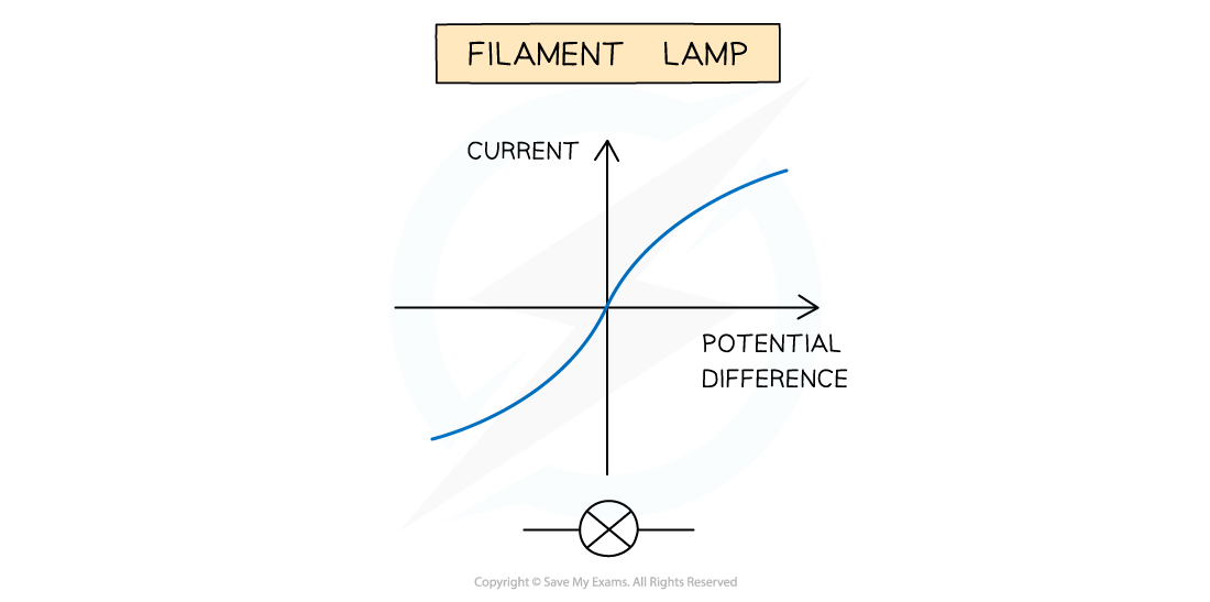
As current flows through a filament lamp, the lamp heats up; resistance increases with temperature, causing the S-shaped curve
As current through a filament lamp increases, the resistance increases because:
the higher current causes the temperature of the filament to increase
the higher temperature causes the atoms in the metal lattice of the filament to vibrate more
this causes an increase in resistance as it becomes more difficult for free electrons (the current) to pass through
since resistance opposes the current, this causes it to increase at a slower rate
I-V graph for a diode
A diode allows current to flow in one direction only
This is called forward bias
In the reverse direction, the diode has very high resistance, and therefore no current flows
This is called reverse bias
When the current is in the direction of the arrowhead symbol, this is forward bias
On the IV graph, this is shown by a sharp increase in voltage and current on the right side of the graph
This shows the resistance is very low
When the diode is switched around, this is reverse bias
On the IV graph, this is shown by a zero reading of current or voltage on the left side of the graph
This shows the resistance is very high
I-V graph for a diode

The current is zero at all potential differences in the negative quadrants because current only flows one way through a diode; this gives the diode I-V graph its distinct shape
Examiner Tips and Tricks
In your IGCSE exam, you could be asked to recognise, sketch or explain the I-V graphs for a wire / fixed resistor (ohmic conductors), a filament lamp and a diode.

You've read 0 of your 5 free revision notes this week
Sign up now. It’s free!
Did this page help you?