1
4 marks
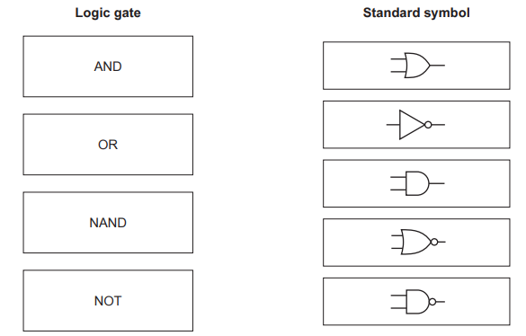
Four logic gates and five standard symbols for logic gates are shown
Draw one line to link each logic gate to its standard symbol. Not all standard symbols will be used.
Was this exam question helpful?
Exam code: 0478 & 0984
Four logic gates and five standard symbols for logic gates are shown
Draw one line to link each logic gate to its standard symbol. Not all standard symbols will be used.
Was this exam question helpful?
Complete the truth table in Fig. 1 for the Boolean statement P = NOT(A AND B).
A | B | P |
|---|---|---|
0 | 0 | 1 |
0 | 1 | |
1 | 0 | |
1 | 1 | 0 |
Fig. 1
Complete the truth table for the following logic gate.

A | B | Q |
|---|---|---|
0 | 0 | 0 |
0 | 1 | 1 |
0 | ||
1 |
Was this exam question helpful?
Consider this logic expression.
X = ( A AND B ) OR ( B AND NOT C )
Draw a logic circuit for this logic expression.
Each logic gate must have a maximum of two inputs.
Do not simplify this logic expression.

Complete the truth table from the given logic expression.
A | B | C | Working space | X |
|---|---|---|---|---|
0 | 0 | 0 | ||
0 | 0 | 1 | ||
0 | 1 | 0 | ||
0 | 1 | 1 | ||
1 | 0 | 0 | ||
1 | 0 | 1 | ||
1 | 1 | 0 | ||
1 | 1 | 1 |
Was this exam question helpful?
Write the Boolean expression represented by the logic diagram below:

Was this exam question helpful?
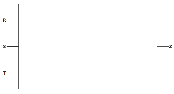
Consider the logic expression:
Z = (R OR NOT T) XOR (NOT S AND T)
Draw a logic circuit for this logic expression.
Each logic gate must have a maximum of two inputs.
Do not simplify this logic expression.
Complete the truth table from the given logic expression.
|
|
|
|
|
|---|---|---|---|---|
|
|
| ||
|
|
| ||
|
|
| ||
|
|
| ||
|
|
| ||
|
|
| ||
|
|
| ||
|
|
|
Was this exam question helpful?
Consider the truth table:
A | B | C | X |
|---|---|---|---|
0 | 0 | 0 | 0 |
0 | 0 | 1 | 0 |
0 | 1 | 0 | 0 |
0 | 1 | 1 | 0 |
1 | 0 | 0 | 1 |
1 | 0 | 1 | 0 |
1 | 1 | 0 | 0 |
1 | 1 | 1 | 1 |
Draw a logic circuit to represent the given truth table.
Each logic gate should have maximum of two inputs.
Do not simplify the logic circuit.

Write a logic expression for the given truth table.
Do not simplify the logic expression.
Was this exam question helpful?
Consider this logic expression.
Z = (NOT A OR B) AND (B XOR C)
Draw a logic circuit for this logic expression.
Each logic gate must have a maximum of two inputs.
Do not simplify this logic expression.

Complete the truth table from the given logic expression.
A | B | C | Working space | X |
|---|---|---|---|---|
0 | 0 | 0 | ||
0 | 0 | 1 | ||
0 | 1 | 0 | ||
0 | 1 | 1 | ||
1 | 0 | 0 | ||
1 | 0 | 1 | ||
1 | 1 | 0 | ||
1 | 1 | 1 |
Was this exam question helpful?
Consider this logic expression.
X = (A OR B) AND (NOT B AND C)
Complete the truth table for this logic expression.
A | B | C | Working space | X |
|---|---|---|---|---|
0 | 0 | 0 | ||
0 | 0 | 1 | ||
0 | 1 | 0 | ||
0 | 1 | 1 | ||
1 | 0 | 0 | ||
1 | 0 | 1 | ||
1 | 1 | 0 | ||
1 | 1 | 1 |
Was this exam question helpful?
Consider the following logic statement:
X = ((A OR B) AND (NOT (B XOR C)) AND C)
Draw a logic circuit to represent the given logic statement.
Do not attempt to simplify the logic statement. All logic gates must have a maximum of two inputs.

Complete the truth table for the given logic statement.
A | B | C | Working space | X |
|---|---|---|---|---|
0 | 0 | 0 | ||
0 | 0 | 1 | ||
0 | 1 | 0 | ||
0 | 1 | 1 | ||
1 | 0 | 0 | ||
1 | 0 | 1 | ||
1 | 1 | 0 | ||
1 | 1 | 1 |
Was this exam question helpful?
Consider the following logic statement:
X = (((A AND NOT B) OR (NOT (B NOR C))) AND C)
Draw a logic circuit to represent the given logic statement.
Do not attempt to simplify the logic statement. All logic gates must have a maximum of two inputs.

Complete the truth table for the given logic statement.
A | B | C | Working space | X |
|---|---|---|---|---|
0 | 0 | 0 | ||
0 | 0 | 1 | ||
0 | 1 | 0 | ||
0 | 1 | 1 | ||
1 | 0 | 0 | ||
1 | 0 | 1 | ||
1 | 1 | 0 | ||
1 | 1 | 1 |
Was this exam question helpful?