Investigating I-V Characteristics (WJEC GCSE Science (Double Award)) : Revision Note

Specified Practical: Investigating I-V Characteristics
Aim of the Experiment
The aim of the experiment is to construct appropriate circuits to investigate the I–V characteristics of a variety of circuit components
These include a fixed resistor at a constant temperature, a lamp and diode
Variables:
Independent variable = Voltage, V
Dependent variable = Current, I
Control variables:
Voltage of the power supply
Use of the same equipment eg. wires, diodes
Equipment List
List of Equipment Used to Investigate the I-V Characteristics of a Range of Circuit Components
Equipment | Purpose |
|---|---|
Ammeter | To measure the current |
Voltmeter | To measure the voltage |
Variable resistor | To change the amount of current in the circuit |
Fixed resistor (between 100 Ω and 500 Ω) | To determine the resistance of |
Diode | To determine the resistance of |
Filament lamp | To determine the resistance of |
Voltage supply | To drive the current around the circuit |
Wires | To complete a closed circuit |
Method
Circuit Diagram of Set-up to Investigate I-V Characteristics of Components

Circuit diagram of the apparatus set up. The fixed resistor will be replaced by a filament lamp and diode
Set up the circuit as shown with the fixed resistor
Vary the current across the component by changing the resistance of the variable resistor, this will change the voltage across the component
For each voltage, record the value of the current from the ammeter 3 times and calculate the average current
Repeat steps 2 and 3 for 8-10 different voltage values increasing by around 0.5 V each time
Make sure to switch off the circuit in between readings to prevent heating of the component and wires
Reverse the terminals of the power supply and take readings for the negative voltage (and therefore negative current)
Replace the fixed resistor with the filament lamp, then the diode, repeating the experiment for each
Example Results Table

A good results table includes space for all measurements and associated calculations (like averages) presented in a clear and logical way
Analysis of Results
Plot a graph of average current against voltage (an I–V graph) for each component
If the I–V graph is a straight line, it is a linear conductor. This is expected from the fixed resistor
If the I–V graph is a curve, it is a non-linear conductor. This is expected from the filament lamp and diode
Compare the results from the graphs obtained to the known I–V graphs for the resistor, filament lamp and diode. These should look like:
I-V Graph Shapes for a Resistor, Diode & Filament Lamp
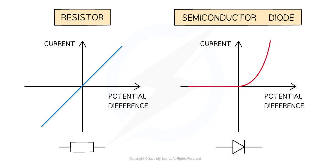
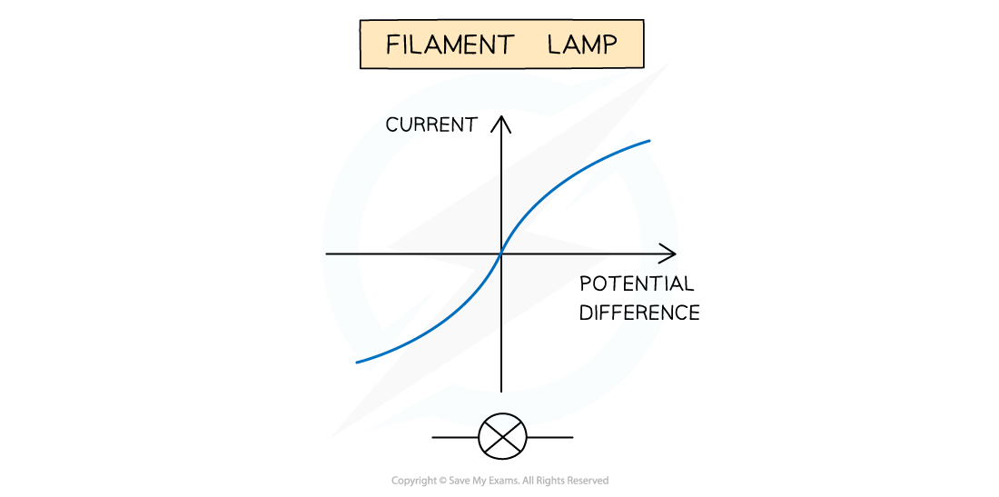
The expected I-V graphs for the resistor, diode and filament lamp
Evaluating the Experiment
Systematic Errors:
The voltmeter and ammeters should start from zero, to avoid zero error in the readings
Random Errors:
In practice, the voltmeter and ammeter will still have some resistance, therefore the voltages and currents displayed may be slightly inaccurate
The temperature of the equipment could affect its resistance. This must be controlled carefully
Taking multiple readings of the current for each component will provide a more accurate result and reduce uncertainties
Safety Considerations
When there is a high current and a thin wire, the wire will become very hot
Make sure you never touch the wire directly when the circuit is switched on
Switch off the power supply right away if burning is smelled
Make sure there are no liquids close to the experiment, as this could damage the electrical equipment
Electrical components will get hot, especially at higher voltages
Be careful when handling them - especially the filament lamp
Disconnect the power supply in between readings to avoid the components heating up too much
Worked Example
A student is given an unknown circuit component in a sealed box, and asked to identify it using its I-V characteristics.
(a) Complete the labels on the circuit diagram.

(b) The student's data is shown in the table below. Suggest the identity of the circuit component and explain your answer.
Voltage (V) | −0.4 | −0.2 | 0.0 | 0.2 | 0.4 | 0.6 | 0.8 | 1.0 |
Current (mA) | 0 | 0 | 0 | 0 | 0 | 4 | 16 | 40 |
Answer:
Part (a)
(i) Resistor
(ii) Cell
(iii) Variable resistor
(iv) Voltmeter
(v) Ammeter
Part (b)
Step 1: Suggest the identify of the circuit component
Diode / LED
Step 2: Explain your answer
The data shows zero current for negative voltages which shows that the current only flows in one direction
The data shows an exponential increase in current for positive voltages
Both of these are features of the I-V characteristics of a diode

You've read 0 of your 5 free revision notes this week
Sign up now. It’s free!
Did this page help you?