I-V Characteristics (WJEC GCSE Science (Double Award)) : Revision Note

I-V Characteristics
I-V characteristics are just the relationship between current,
 , and voltage,
  , for different components
These relationships are often shown by I-V graphs
Circuit components can be linear or non-linear
In maths, linear means the graph is a straight line
Linear components have an I-V graph that is a straight line through the origin
Non-linear components have an I-V graph that is not a straight line
Linear and Non-linear I-V Graphs

Linear I-V graphs have a straight line going through the origin, this shows a constant resistance. Non-linear I-V graphs have curved lines showing a changing resistance
If current and voltage are directly proportional, then as one increases, the other increases by the same amount
When I-V graphs are directly proportional, this means that the resistance R remains constant
Linear components include:
Fixed resistors (at constant temperature)
Wires (at constant temperature)
Non-linear components include:
Filament lamps
Diodes & LEDs
LDRs
Thermistors
Resistance in Filament Lamps & Diodes
In order to investigate the variation of resistance in a filament lamp or diode, the following circuits should be set up:
Circuits Used to Investigate Resistance of a Filament Lamp and a Diode

These circuits enable the variation of resistance in a filament lamp or a diode to be investigated
The current is the independent variable
The variable resistor is used to change the current flowing through the filament lamp / diode
The voltage is the dependent variable
The voltmeter is used to measure the voltage across the filament lamp / diode
Recording measurements of current and voltage as the current increases enables an IV graph to be plotted for each component
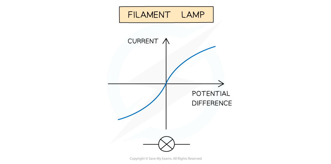
I-V Characteristics of a Filament Lamp
For a filament lamp the current and voltage are not directly proportional
The I–V graph shows the current increasing at a proportionally slower rate than the voltage
I-V Graph of a Filament Lamp
The resistance changes with temperature for a filament lamp
This is because:
As the current increases, the temperature of the filament in the lamp increases
The higher temperature causes the atoms in the metal lattice of the filament to vibrate more
This causes an increase in resistance as it becomes more difficult for free electrons (the current) to pass through
Resistance opposes the current, causing the current to increase at a slower rate
Where the graph is a straight line, the resistance is constant
The resistance increases as the graph curves
Reversing the voltage reverses the current and makes no difference to the shape of the curve
I-V Characteristics of a Diode
A diode is a non-linear conductor that allows current to flow in one direction only
The direction is shown by the triangular arrow of the diode symbol
This is called forward bias
In the reverse direction, the diode has very high resistance, and therefore no current flows
This is called reverse bias
The I–V graph for a diode has a unique shape
When the diode is in forward bias, the graph shows a sharp increase in voltage and current (on the right side of the graph)
When the diode is switched around, in reverse bias, the graph shows a flat line where current is zero at all voltages (on the left side of the graph)
I-V Graph of a Diode

A diode only allows current to flow in one direction which gives the I-V graph a distinct shape
Resistance in LDRs & Thermistors
In order to investigate the variation of resistance in an LDR or a thermistor, the following circuits should be set up:
Circuits Used to Investigate Resistance in an LDR and a Thermistor
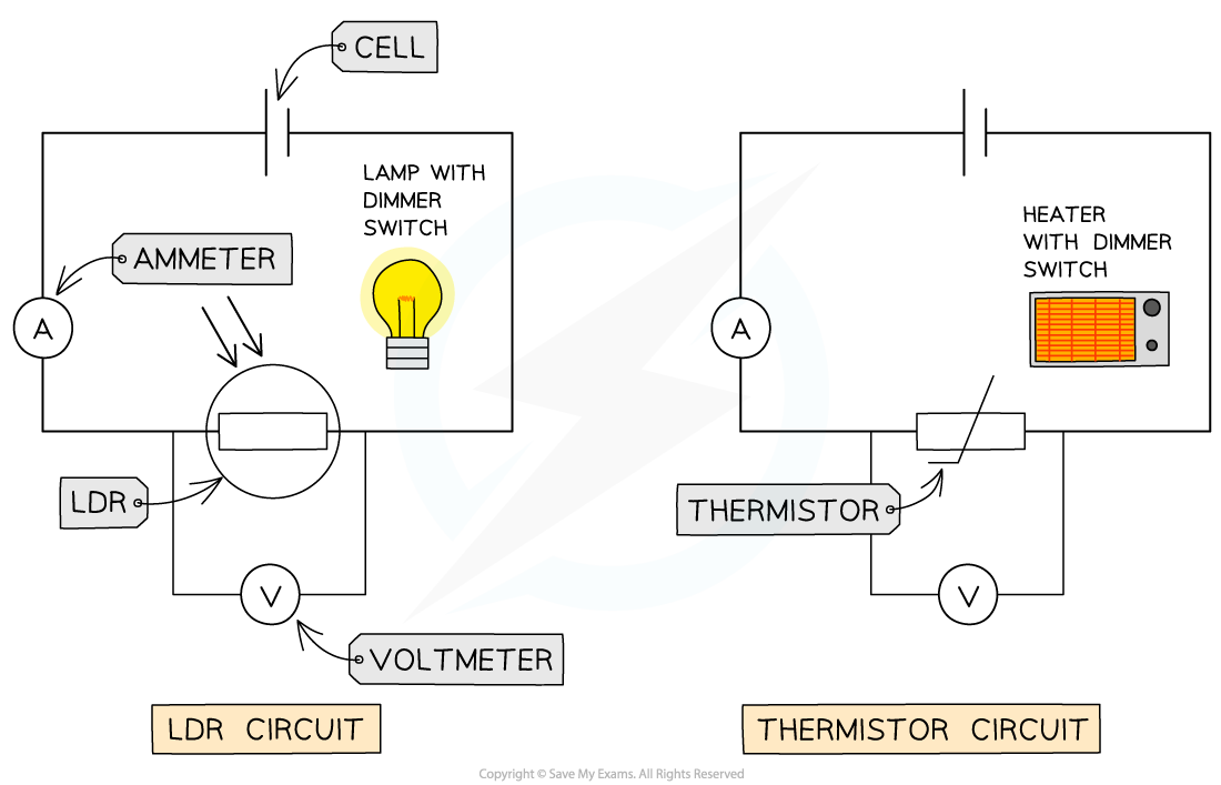
These circuits enable the variation of resistance in a LDR or a thermistor to be investigated
For the LDR circuit:
Begin with the lamp turned off in a dark room
Record the reading on the voltmeter and ammeter
Slowly increase the light intensity of the lamp using the dimmer switch
Record the reading on the voltmeter and ammeter for each increase in light intensity
For the thermistor circuit:
Begin with the heater turned off
Record the reading on the voltmeter and ammeter
Slowly increase the temperature of the heater using the dimmer switch
Record the reading on the voltmeter and ammeter for each increase in temperature of the heater
In both situations, make sure the lamp and heater are close to, but not touching, the LDR and thermistor respectively
Wait a few seconds before taking the voltmeter and ammeter readings to allow the LDR and thermistor to react to the change in the environment
Plot an I-V graph to show the resistance of each component
Examiner Tips and Tricks
It's really common for examiners to test your understanding of setting up and using a circuit to measure current, voltage and resistance of a component. Generally, make sure the following are included in your circuit diagrams:
The ammeter is connected in series to the component
The voltmeter is connected in parallel to the component
The correct symbol is used for each component
If you need to vary the current, include a variable resistor
The component is connected to a power supply with a low voltage otherwise the heating effects of the current will start to affect the resistance of the component

Circuit diagram for measuring the variation of resistance of a component, using current and voltage

You've read 0 of your 5 free revision notes this week
Sign up now. It’s free!
Did this page help you?