I–V Graphs (OCR GCSE Combined Science A (Gateway)) : Revision Note
Linear & Non-Linear Graphs
As the potential difference (voltage) across a component is increased, the current also increases (by Ohm’s law)
The precise relationship between voltage and current is different for different components and can be shown on an I-V graph
This is known as the I-V characteristic of the component
Circuit components can have I-V characteristic graphs that are linear or non-linear
In maths, linear means the graph is a straight line
To know whether a circuit element is linear or non-linear, check whether its I-V graphs is a straight line or not
Linear components have an I-V graph that is a straight line
Non-linear components have an I-V graph that is not a straight line
Linear graphs that go through the origin show a directly proportional relationship
Linear components are said to obey Ohm's Law and have a constant resistance, whilst non-linear do not
Some components may be linear at low currents, then become non-linear as the current increases (and therefore a change in temperature)
For example, a fixed resistor at room temperature is linear, but when it becomes very hot it will become non-linear

Linear and non-linear I-V graphs
Components with linear I-V characteristics include:
Fixed resistors
Wires
Heating elements
Components with non-linear I-V characteristics include:
Filament lamps
Diodes & LEDs
LDRs
Thermistors
I-V Characteristics
Fixed Resistors
The current through a fixed resistor increases as the potential difference across it increases
In other words, current is directly proportional to the potential difference for a fixed resistor
An I-V graph shows that the line is straight and goes through the origin, as shown in the I-V graph below:

I-V graph for a fixed resistor. The current is directly proportional to the potential difference as the graph is a straight line through the origin
This relationship is true because the resistance of a fixed resistor is constant
Filament Lamps
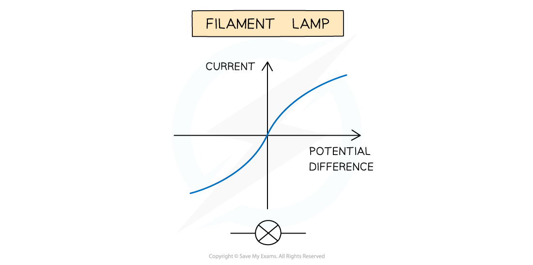
For a filament lamp, current and potential difference are not directly proportional
This is because the resistance of the filament lamp increases as the temperature of the filament increases
The I–V graph for a filament lamp shows the current increasing at a proportionally slower rate than the potential difference

I-V graph for a filament lamp
This is because:
As the current increases, the temperature of the filament in the lamp increases
The higher temperature causes the atoms in the metal lattice of the filament to vibrate more
This causes an increase in resistance as it becomes more difficult for free electrons (the current) to pass through
Resistance opposes the current, causing the current to increase at a slower rate
Where the graph is a straight line, the resistance is constant
The resistance increases as the graph curves
Reversing the potential difference reverses the current and makes no difference to the shape of the curve
Diodes
A diode allows current to flow in one direction only
This is called forward bias
In the reverse direction, the diode has very high resistance, and therefore no current flows
This is called reverse bias

I-V graph for a semiconductor diode
The I–V graph for a diode is slightly different:
When the current is in the direction of the arrowhead symbol, this is forward bias
This is shown by the sharp increase in potential difference and current on the right side of the graph
When the diode is switched around, this is reverse bias
This is shown by a zero reading of current or potential difference on the left side of the graph
Worked Example
The I–V characteristic of two electrical component X and Y are shown.

Which statement is correct?
A. The resistance of X increases as the current increases
B. At 2 V, the resistance of X is half the resistance of Y
C. Y is a semiconductor diode and X is a resistor
D. X is a resistor and Y is a filament lamp
Answer: C
The I-V graph X is linear
This means the graph has a constant gradient. I/V and the resistance is therefore also constant (since gradient = 1/R)
This is the I-V graph for a conductor at constant temperature e.g. a resistor
The I-V graph Y starts with zero gradient and then the gradient increases rapidly
This means it has infinite resistance at the start which then decreases rapidly
This is characters of a device that only has current in one direction e.g a semiconductor diode
Therefore the answer is C
Examiner Tips and Tricks
In your examination, you may be asked to plot, analyse or compare different I-V characteristic graphs for different components. It is a good idea to learn the shape of the graphs for the components mentioned above and what this means in terms of the relationship between current and potential difference.

You've read 0 of your 5 free revision notes this week
Unlock more, it's free!
Did this page help you?
