Electrical Components (Edexcel GCSE Combined Science: Physics): Revision Note
Exam code: 1SC0

Written by: Ashika
Updated on
Did this video help you?
I-V Graphs
Fixed Resistors
The current through a fixed resistor increases as the potential difference across it increases
In other words, current is directly proportional to the potential difference for a fixed resistor
An I-V graph shows that the line is straight and goes through the origin, as shown in the I-V graph below:

I-V graph for a fixed resistor. The current is directly proportional to the potential difference as the graph is a straight line through the origin
This relationship is true because the resistance of a fixed resistor is constant
Filament Lamps
For a filament lamp, current and potential difference are not directly proportional
This is because the resistance of the filament lamp increases as the temperature of the filament increases
The I–V graph for a filament lamp shows the current increasing at a proportionally slower rate than the potential difference
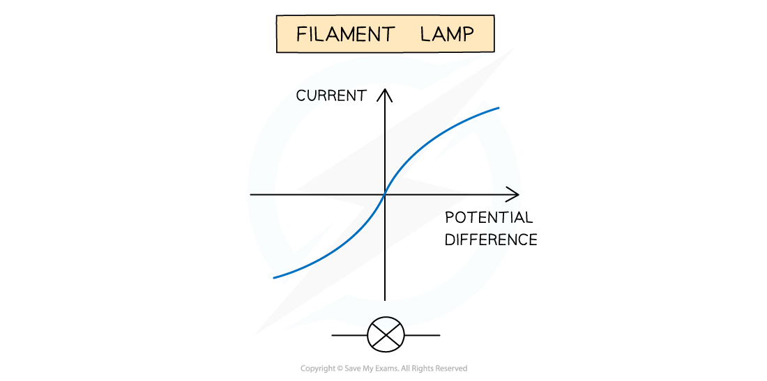
I-V graph for a filament lamp
This is because:
As the current increases, the temperature of the filament in the lamp increases
The higher temperature causes the atoms in the metal lattice of the filament to vibrate more
This causes an increase in resistance as it becomes more difficult for free electrons (the current) to pass through
Resistance opposes the current, causing the current to increase at a slower rate
Where the graph is a straight line, the resistance is constant
The resistance increases as the graph curves
Reversing the potential difference reverses the current and makes no difference to the shape of the curve
Diodes
A diode allows current to flow in one direction only
This is called forward bias
In the reverse direction, the diode has very high resistance, and therefore no current flows
This is called reverse bias

I-V graph for a semiconductor diode
The I–V graph for a diode is slightly different:
When the current is in the direction of the arrowhead symbol, this is forward bias
This is shown by the sharp increase in potential difference and current on the right side of the graph
When the diode is switched around, this is reverse bias
This is shown by a zero reading of current or potential difference on the left side of the graph
Examiner Tips and Tricks
Make sure to practice drawing which current-voltage graph is for which component, as this is a common exam question!
Did this video help you?
LDRs
A light-dependent resistor (LDR) is a type of sensory resistor
This means it is a resistor which has a resistor that changes with its surroundings
The circuit symbol for an LDR is:

LDR circuit symbol
The resistance of an LDR changes depending on the light intensity on it
As the light intensity increases the resistance of an LDR decreases and vice versa

The resistance of an LDR is dependent on the amount of light intensity on it
LDRs can be used as light sensors, so, they are useful in circuits which automatically switch on lights when it gets dark, for example, street lighting and garden lights
Thermistors
A thermistor is also a type of sensory resistor
It is represented by the following circuit symbol:

Thermistor circuit symbol
The resistance of a thermistor changes depending on its temperature
As the temperature increases the resistance of a thermistor decreases and vice versa

The resistance through a thermistor is dependent on temperature
Thermistors are temperature sensors and are used in circuits in ovens, fire alarms and digital thermometers
As the thermistor gets hotter, its resistance decreases
As the thermistor gets cooler, its resistance increases

A digital thermometer uses a thermistor
Examiner Tips and Tricks
Here is a list of all the circuit symbols you need to know for your exam:


Unlock more, it's free!
Join the 100,000+ Students that ❤️ Save My Exams
the (exam) results speak for themselves:

Was this revision note helpful?