Testing Components (Edexcel GCSE Physics) : Revision Note
Testing Components
The GCSE examination will require an understanding of the variation of resistance in the following devices:
Filament lamps
Diodes
Thermistors
LDRs
Luckily, the design and use of the circuits to investigate how resistance varies is broadly similar for each component
Resistance in Filament Lamps & Diodes
In order to investigate the variation of resistance in a filament lamp or diode, the following circuits should be set up:
The current is the independent variable
The variable resistor is used to change the current flowing through the filament lamp / diode
The voltage is the dependent variable
The voltmeter is used to measure the voltage across the filament lamp / diode
Calculate the resistance of the filament lamp / diode for each chosen value of current and measured value of voltage using the equation:


These circuits enable the variation of resistance in a filament lamp or a diode to be investigated
Resistance in LDRs & Thermistors
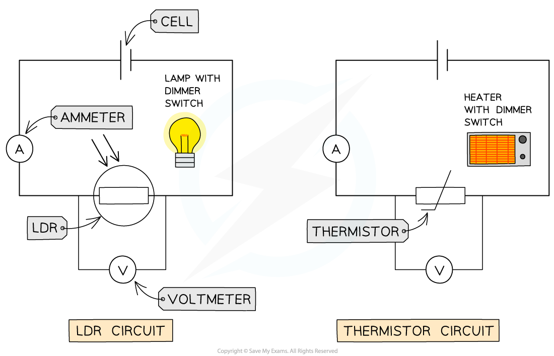
In order to investigate the variation of resistance in a LDR or a thermistor, the following circuits should be set up:

These circuits enable the variation of resistance in a LDR or a thermistor to be investigated
For the LDR circuit:
Begin with the lamp turned off in a dark room
Record the reading on the voltmeter and ammeter
Slowly increase the light intensity of the lamp using the dimmer switch
Record the reading on the voltmeter and ammeter for each increase in light intensity
For the thermistor circuit:
Begin with the heater turned off
Record the reading on the voltmeter and ammeter
Slowly increase the temperature of the heater using the dimmer switch
Record the reading on the voltmeter and ammeter for each increase in temperature of the heater
In both situations, make sure the lamp and heater are close, but not touching, the LDR and thermistor respectively
Wait a few seconds before taking the voltmeter and ammeter readings to allow the LDR and thermistor to react to the change in the environment
Calculate the resistance of the LDR or thermistor for each change in light intensity or temperature using the equation:

Examiner Tips and Tricks
It's really common for examiners to test your understanding of setting up and using a circuit to measure current, voltage and resistance of a component. Generally, make sure the following are included in your circuit diagrams:
The ammeter is connected in series to the component
The voltmeter is connected in parallel to the component
The component with the appropriate circuit symbol
If you need to vary the current, include a variable resistor
The component is connected to a power supply with a low voltage (below 15 V) otherwise too high a current in the circuit will start to affect the resistance of the component

Circuit diagram for measuring the variation of resistance of a component, using current and voltage

You've read 0 of your 5 free revision notes this week
Sign up now. It’s free!
Did this page help you?
