Investigating Resistance in Thermistors & LDRs (AQA GCSE Physics): Revision Note
Exam code: 8463
Investigating Resistance in Thermistors & LDRs
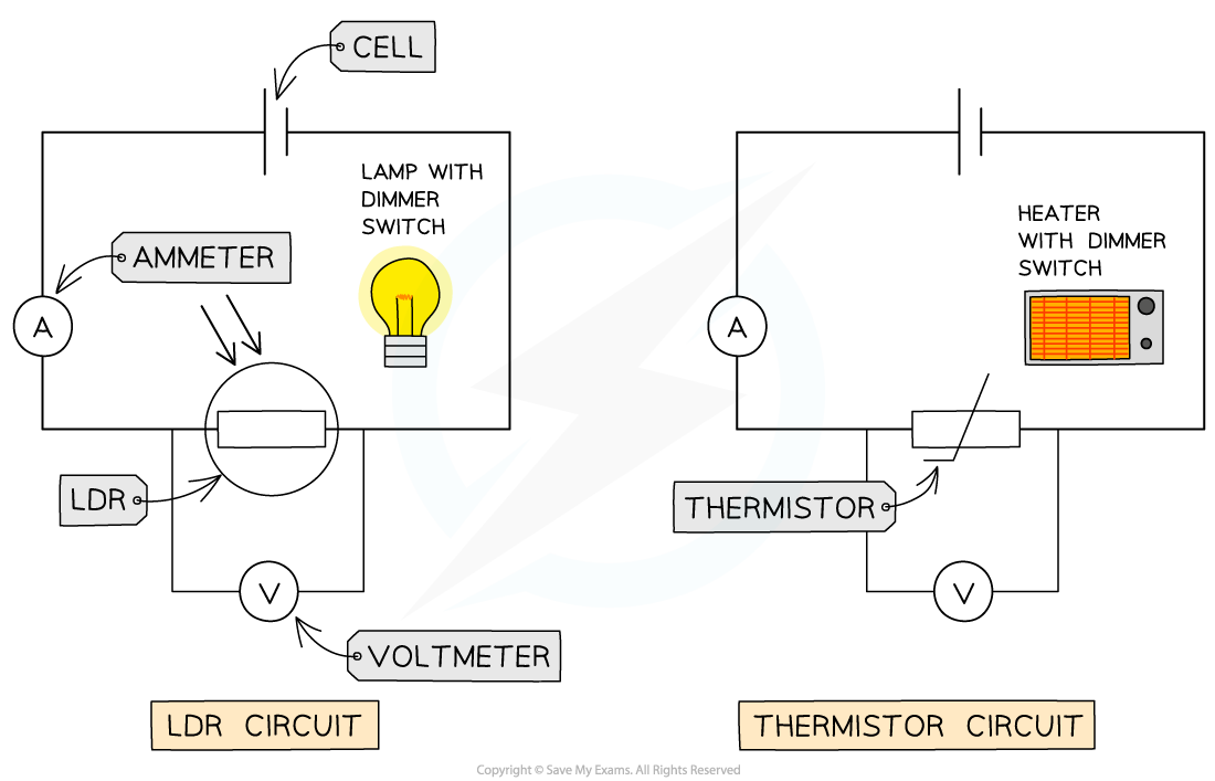
To investigate the relationship between the resistance of a thermistor and temperature, or the resistance of an LDR and light intensity, the following circuits must be set up:

For the LDR circuit:
Begin with the lamp turned off in a dark room
Record the reading on the voltmeter and ammeter
Slowly increase the light intensity of the lamp using the dimmer switch
Record the reading on the voltmeter and ammeter for each increase in light intensity
For the thermistor circuit:
Begin with the heater turned off
Record the reading on the voltmeter and ammeter
Slowly increase the heat of the heater using the dimmer switch
Record the reading on the voltmeter and ammeter for each increase in temperature of the heater
In both situations, make sure the lamp and heater are close, but not touching, the LDR and thermistor respectively
Wait a few seconds before taking the voltmeter and ammeter readings to allow the LDR and thermistor to react to the change in the environment
Calculate the resistance of the LDR or thermistor for each change in light intensity or temperature using the equation:

Therefore, to measure the resistance of any component in a circuit, make sure the following are included in the circuit diagrams:
The ammeter is connected in series to the component
The voltmeter is connected in parallel to the component
The component with the appropriate circuit symbol
The component is connected to a power supply with a low voltage (below 15 V) otherwise too high a current in the circuit will start to affect the resistance of the component

Circuit diagram for investigating the resistance of a component
Examiner Tips and Tricks
Make sure to draw all the circuit symbols accurately. Many of them are very similar with small differences denoting what they do:
Two arrows pointing towards a symbol mean that it is light-dependent (eg. LDR)
Two arrows pointing away mean that it is light-emitting (eg. LED)

Unlock more, it's free!
Did this page help you?