Circuit Diagrams (AQA GCSE Physics): Revision Note
Exam code: 8463
Circuit Diagrams
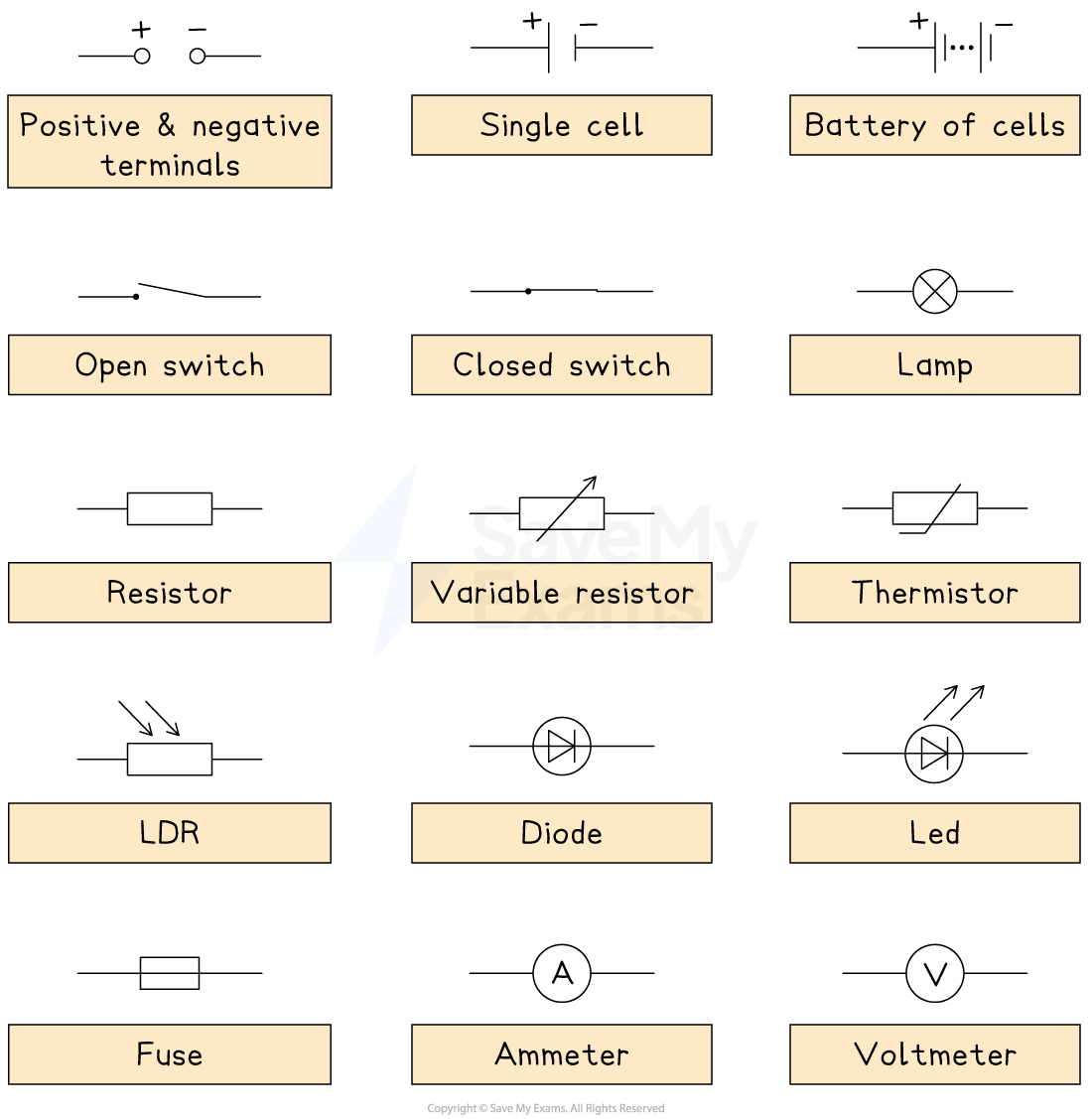
All students in the GCSE examination will be expected to recognise the following standard symbols and be able to construct circuits using them:

The function of the most common components are:
Cell / battery: Provides the circuit with a source of potential difference. A battery is two or more cells
Switch: Turn the circuit on (closed), or off (open)
Fixed resistor: A resistor limits the flow of current. A fixed resistor has a resistance it cannot change
Variable resistor: A resistor with a slider that can be used to change its resistance. These are often used in dimmer switches and volume controls
Thermistor: The resistance of a thermistor depends on its temperature. As its temperature increases, its resistance decreases and vice versa
Light-dependent resistor (LDR): The resistance of an LDR depends on the light intensity. As the light intensity increases, its resistance decreases and vice versa
Diode: A diode allows current to flow in one direction only. Current flows through the diode when it is in forward bias position. They are used to convert AC to DC current
Light-emitting diode (LED): This is equivalent to a diode and emits light when a current passes through it. These are used for aviation lighting and displays (TVs, road signs)
Fuse: A safety device designed to cut off the flow of electricity to an appliance if the current becomes too large (due to a fault or a surge) by melting the fuse wire and therefore breaking the circuit
Ammeter: Used to measure the current in a circuit. Connected in series with other components
Voltmeter: Use to measure the potential difference of an electrical component. Connected in parallel with the relevant component
Each of these components have an electrical resistance that may impact the current in the circuit
However, the resistance of the ammeter is taken to be negligible and the resistance of a voltmeter is taken to be infinite in exam questions
Drawing & Interpreting Circuit Diagrams
Being able to draw and interpret circuit diagrams using circuit symbols is an essential skill in the electricity topic
Electric circuit diagrams require the following to work effectively:
An energy source – This is a source of potential difference, so a current can flow. This can be a cell, battery, or a power supply
A closed path or a complete circuit – Electrons need to flow in a complete loop for a current to flow. A circuit can be open and closed using a switch
Electrical components – These could act as sensors that respond to the environment (LDR, thermistor), or measure a value (ammeter, voltmeter), or transfer electrical energy to other forms of energy (LED, lamp). These must be drawn with the correct circuit symbol
The key rules to remember are:
An ammeter is always connected in series
A voltmeter is always connected in parallel to the component the voltage is being measured
The direction of current flow is always from the positive to the negative terminal of the power supply
Worked Example
Which circuit diagram correctly represents a circuit with current flowing through?


For a circuit to be connected, the switch must be closed
This is either circuit B or D
The other circuit symbol is a diode
Diodes only allow current to flow in one direction
Since current flow is from positive to negative, a forward-biased diode must point in this direction in order for the current to flow
This is seen in circuit B
Examiner Tips and Tricks
When asked to draw a circuit diagram, make sure to draw the wires as straight lines with a straight edge or a ruler and make it as neat as possible, especially the circuit symbols.
If the diagram is too small or there is ambiguity as to what a symbol represents, the examiner may not award you full marks!
Students often overlook actively learning the circuit symbols. It is true that you will come to be familiar with most of them as you study the course, but it is really important that as part of your revision, you make sure that you know them all. You need to be able to name them and draw them. And for components such as thermistors, resistors, LDRs, fuses, and diodes, you also need to be able to explain how they work.

Unlock more, it's free!
Did this page help you?