Free-Body Diagrams (DP IB Physics) : Revision Note
Free-Body Diagrams
Forces are pushes or pulls that occur due to the interaction between objects
In physics, during force interactions, it is common to represent situations as simply as possible without losing information
When considering force interactions, objects are represented as point particles
These point particles should be placed at the centre of mass of the object
Forces are represented by arrows because forces are vectors
The length of the arrow gives the magnitude of the force, and its direction gives the force's direction
The below example shows the forces acting on an object when pushed to the right over a rough surface
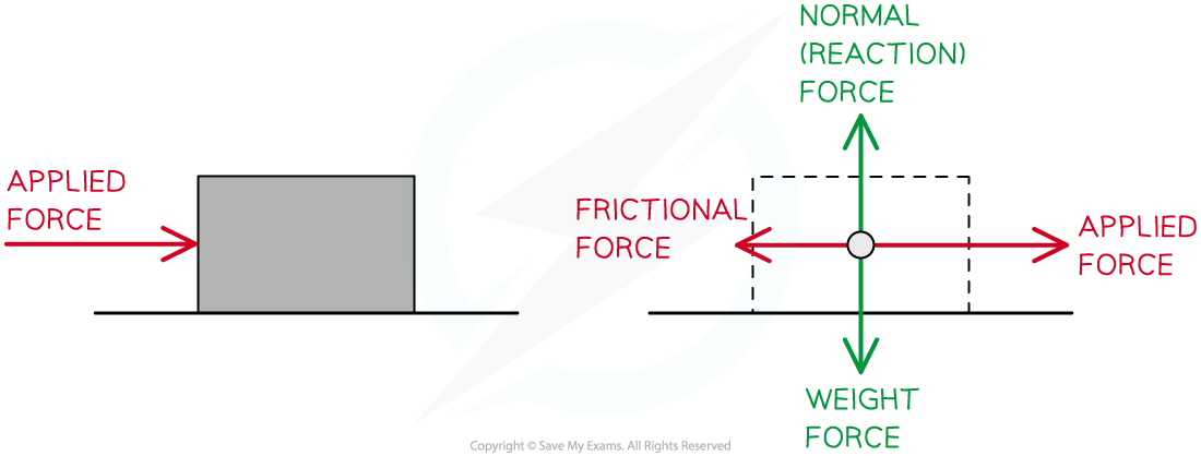
Point particle representation of the forces acting on a moving object
The below example shows the forces acting on an object suspended from a stationary rope
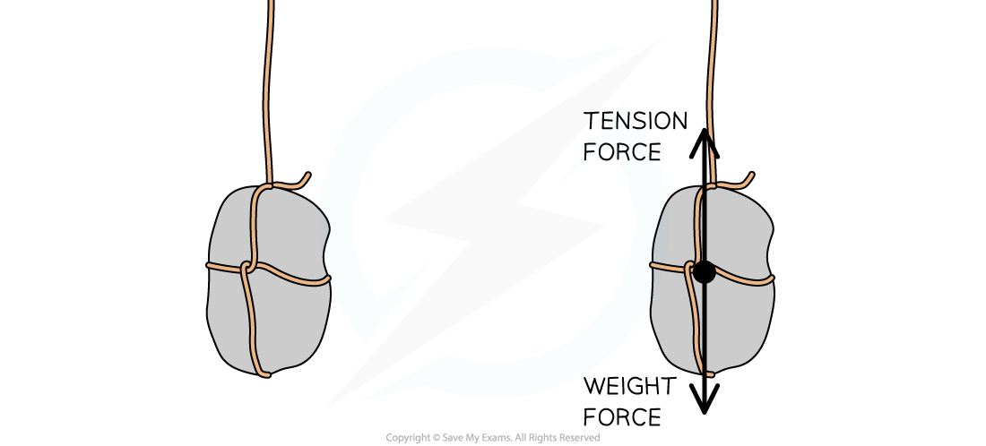
Forces on an object suspended from a stationary rope
Free-body Diagrams
As situations become more complex, there are often multiple forces acting in different directions on multiple objects
To simplify these situations, free-body force diagrams can be used
Free-body force diagrams show:
Multiple forces acting on one object
The direction of the forces
The magnitude of the forces
Each force is represented as a vector arrow
The length of the arrow represents the magnitude of the force
The direction of the arrow shows the direction in which the force acts
Each force arrow is labelled with either:
a description of the type of force acting and the objects interacting with clear cause and effect
The gravitational pull of the Earth on the ball
the name of the force
Weight
an appropriate symbol
Fg
Free body diagrams can be used to:
identify which forces act in which plane
determine the resultant force
The rules for drawing a free-body diagram are:
Multiple forces acting on one object
The object is represented as a point mass
Only the forces acting on the object are included
The forces are drawn in the correct direction
The forces are drawn with proportional magnitudes
The forces are clearly labelled
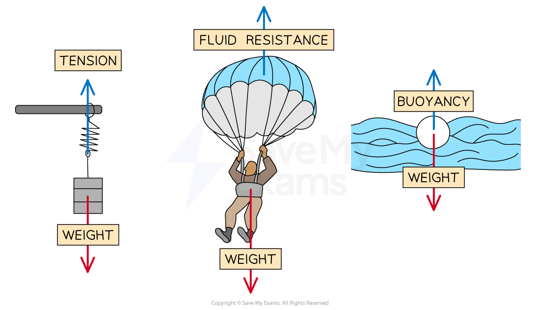

Free-body diagrams for different situations
The most common forces to apply are:
Weight (Fg) - always towards the surface of the planet
Tension (FT) - always away from the mass
Normal Reaction Force (FN) - perpendicular to a surface
Frictional Forces (Ff) - in the opposite direction to the motion of the mass
Worked Example
Draw free-body diagrams for the following scenarios:
(a) A picture frame hanging from a nail.
(b) A box sliding down a slope.
Answer:
(a) A picture frame hanging from a nail:
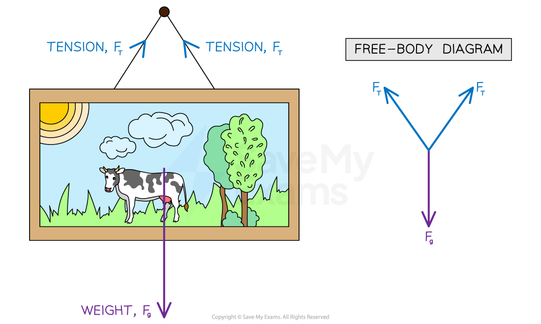
The size of the arrows should be such that the 3 forces would make a closed triangle as they are balanced
(b) A box sliding down a slope:
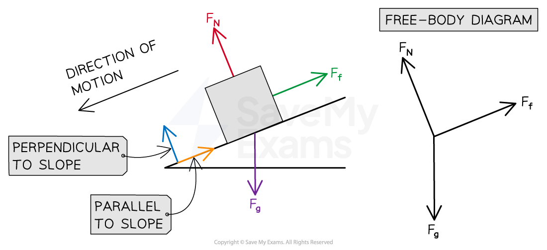
There are three forces acting on the box:
The normal contact force, FN, acts perpendicular to the slope
Friction, Ff, acts parallel to the slope and in the opposite direction to the direction of motion
Weight, Fg, acts down towards the Earth
Worked Example
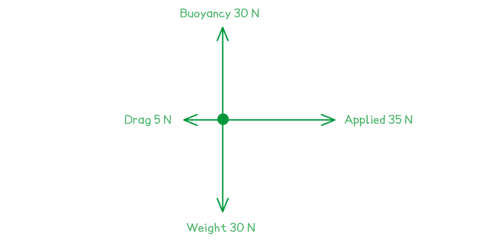
A toy sailboat has a weight of 30 N, and is floating in water. The boat is being pulled to the right with a force of 35 N. The boat has a total resistive force of 5 N.
Draw a free-body force diagram for the toy sailboat.
Answer:
Step 1: Identify all of the forces acting upon the object in question, including any forces that may be implied
Weight = 30 N downward
Buoyancy from the water (as the object is floating) = 30 N upward
Applied force = 35 N to the right
Drag force = 5 N to the left
Step 2: Draw in all of the force vectors (arrows), making sure the arrows start at the object and are directed away
Examiner Tips and Tricks
When labelling force vectors, it is important to use conventional and appropriate naming or symbols such as:
Fg or Weight or mg
FN for normal reaction force
Using unexpected notation will lose you marks.
Make sure your arrows are roughly to scale with respect to the other forces in the image. In the second worked example, the 5 N force arrow needs to be considerably shorter than the 35 N arrow. This shows clearly that there is a resultant force to the right.
Determining Resultant Forces
Free-body diagrams can be analysed to find the resultant force acting within a system
A resultant force is the vector sum of the forces operating on a body
When many forces are applied to an object they can be combined
This produces one overall force, which describes the combined action of all of the forces
This single resultant force determines the change in the object's motion:
The direction in which the object will move as a result of all of the forces
The magnitude of the total force experienced by the object
The resultant force is sometimes called the net force
Forces can combine to produce
Balanced forces
Unbalanced forces
Balanced forces mean that the forces have combined in such a way that they cancel each other out
Then, the resultant force acting on the body is zero
For example, the weight force of a book on a desk is balanced by the normal contact force of the desk
As a result, no resultant force is experienced by the book; the forces acting on the book and the table are equal and balanced
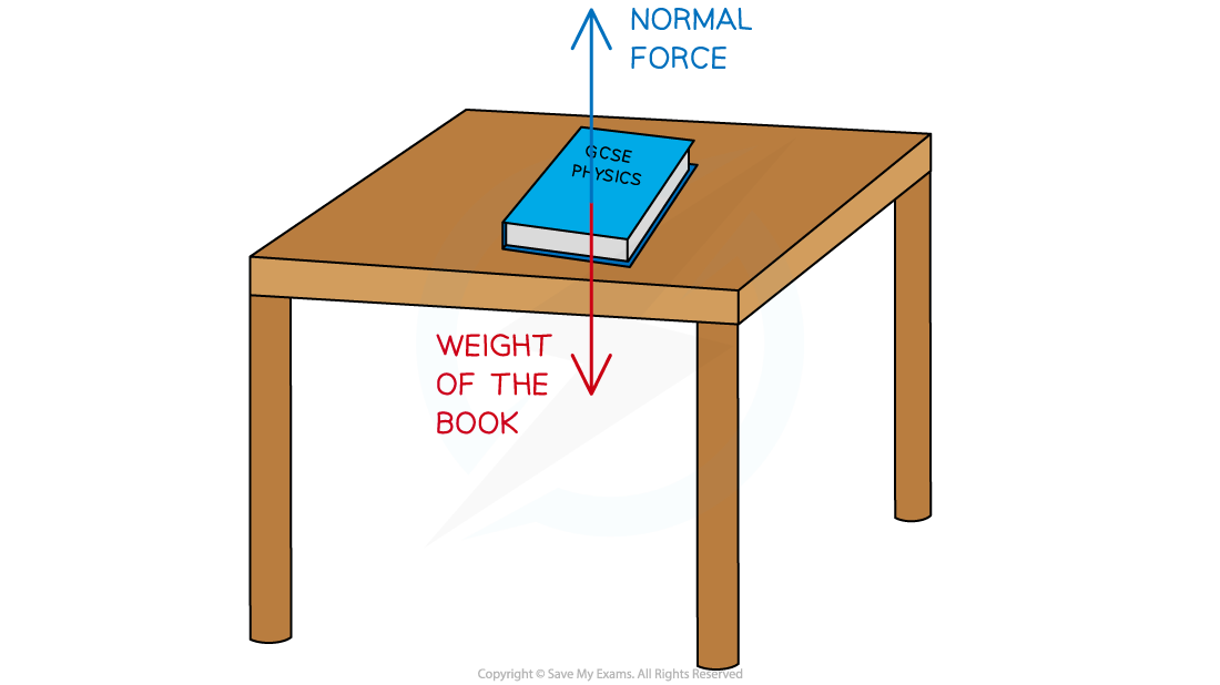
A book resting on a table is an example of balanced forces
Unbalanced forces mean that the forces have combined in such a way that they do not cancel out completely and there is a non-zero resultant force on the object
For example, two people play a game of tug-of-war, working against each other on opposite sides of the rope
If Person A pulls on the rope with a force 80 N to the left and Person B pulls on the rope with a force of 100 N to the right, these forces do not cancel each other out completely
Since Person B pulled with more force than Person A, the forces will be unbalanced, and the rope will experience a resultant force of 20 N to the right
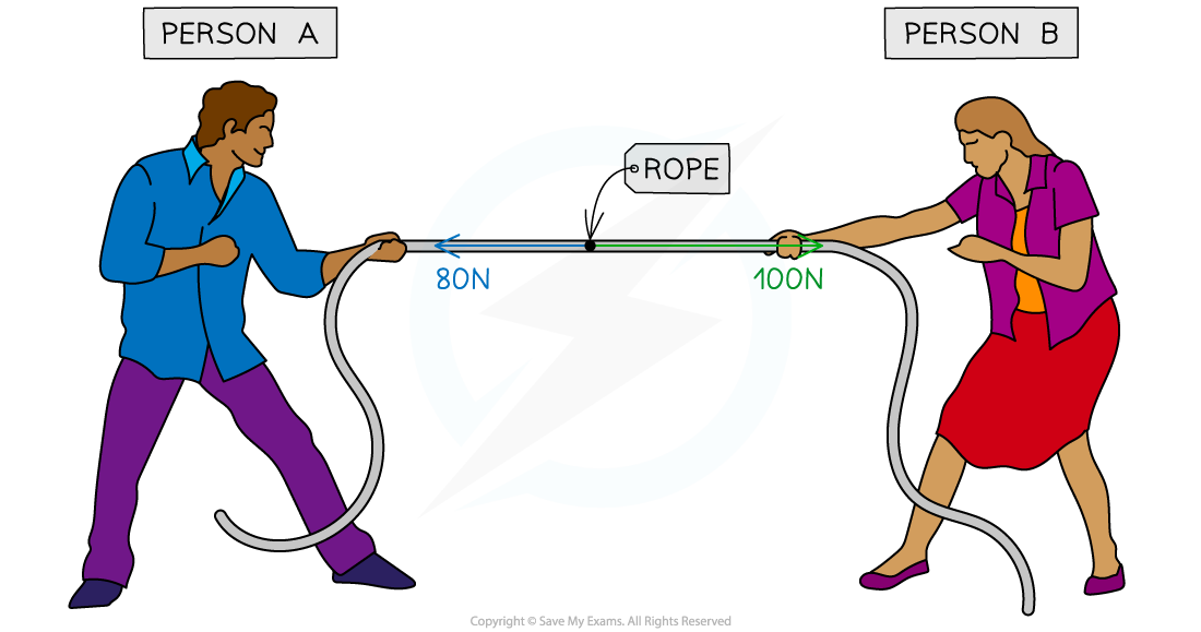
A tug-of-war is an example of when forces can become unbalanced
Resultant forces in one-dimension
The resultant force in a one-dimensional situation i.e. when the forces are directed along the same plane, can be found by combining vectors
Combining force vectors involves adding all of the forces acting on the object taking into account the direction of the forces
This is easiest to visualise when they are drawn as a free-body diagram
If the forces acting in opposite directions are equal in size, then there will be no resultant force
The forces are said to be balanced
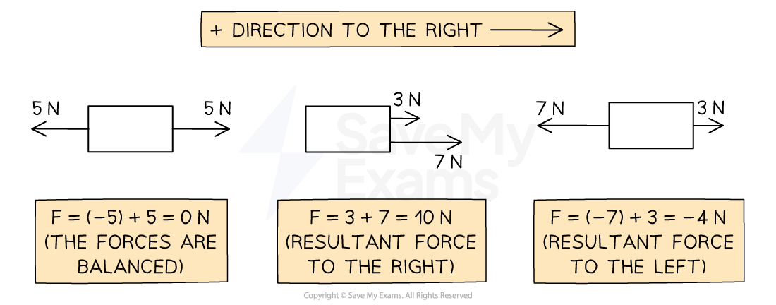
Diagram showing the resultant forces on three different objects
Imagine the forces on the boxes as two people pushing and pulling on either side
In the first scenario, the two people are evenly matched - the box doesn't move
In the second scenario, the two people are pushing on the same side of the box, it moves to the right with their combined strength
In the third scenario, the two people are pushing against each other and are not evenly matched, so there is a resultant force to the left
Resultant forces in two-dimensions
The resultant force in a two-dimensional situation i.e. when the forces are not on the same plane, can be found from resolving vectors
Resolving force vectors involves using Pythagoras or trigonometry to determine the resultant of all of the forces acting on the object
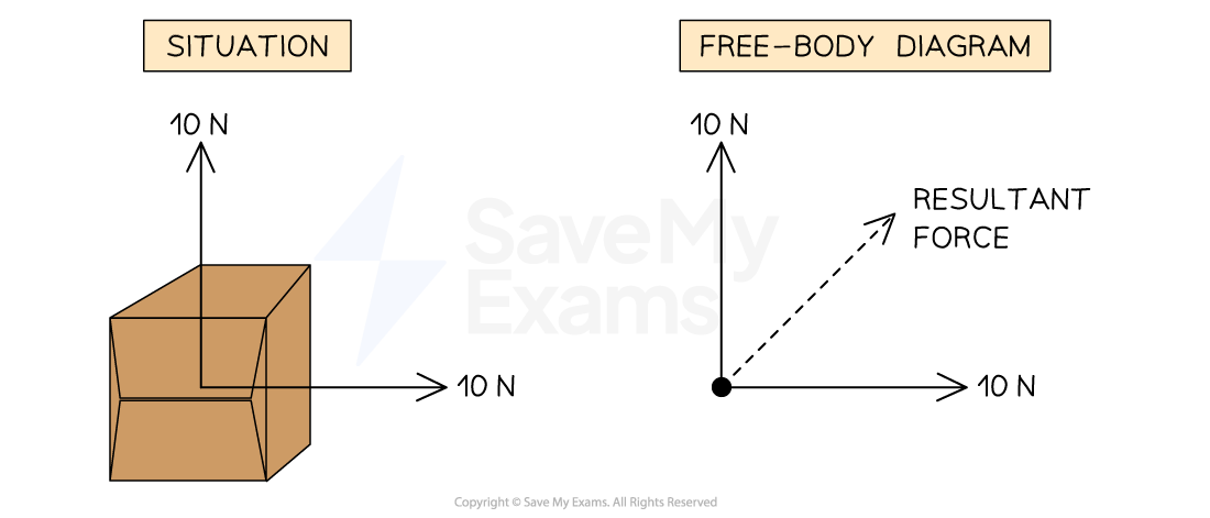
The resultant force is easier to visualise using a free-body diagram
For example, the two 10 N forces acting on the cardboard box produce a resultant force of
More on these calculations can be found in Combining & Resolving Vectors
Worked Example
Calculate the magnitude and direction of the resultant force on the object shown in the diagram below.

Answer:
Step 1: Decide on the direction you will define as positive and negative
Take the right as positive and the left as negative
Step 2: Add up all of the forces
Step 3: Evaluate the direction of the resultant force
Since the resultant force is negative, this is in the negative direction i.e. the left
Step 4: State the magnitude and direction of the resultant force
The resultant force is 2 N to the left
Worked Example
Calculate the magnitude and direction of the resultant force acting on the cardboard box shown in the diagram below.

Answer:
Step 1: Sketch the free-body diagram for the situation
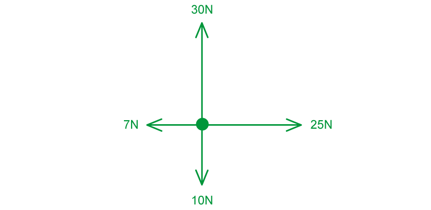
Step 2: Determine the resultant horizontal force
Taking the right as positive
(to the right)
Step 3: Determine the resultant vertical force
Take upwards as positive
(upwards)
Step 4: Calculate the resultant force

Using Pythagoras' theorem
Examiner Tips and Tricks
Take a look at the 'Tools' section of the course to learn how to combine and resolve vectors. You should be comfortable with these calculations for the whole of the forces topic.

You've read 0 of your 5 free revision notes this week
Sign up now. It’s free!
Did this page help you?
