Magnetic Force on a Current-Carrying Conductor (DP IB Physics) : Revision Note
Magnetic Force on a Current-Carrying Conductor
A current-carrying conductor produces its own magnetic field
When interacting with an external magnetic field, it will experience a force
The force F on a conductor carrying current I at an angle θ to a magnetic field with flux density B is defined by the equation
Where:
F = force on a current-carrying conductor in a B field (N)
B = magnetic flux density of applied B field (T)
I = current in the conductor (A)
L = length of the conductor (m)
θ = angle between the conductor and applied B field (degrees)
This equation shows that the force on the conductor can be increased by:
Increasing the strength of the magnetic field
Increasing the current flowing through the conductor
Increasing the length of the conductor in the field
Note: The length L represents the length of the conductor that is within the field
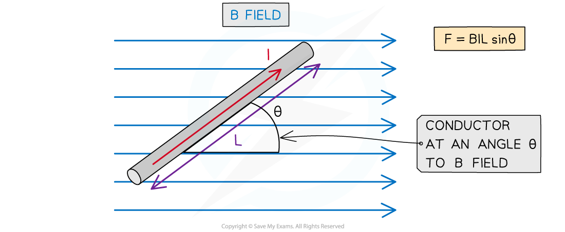
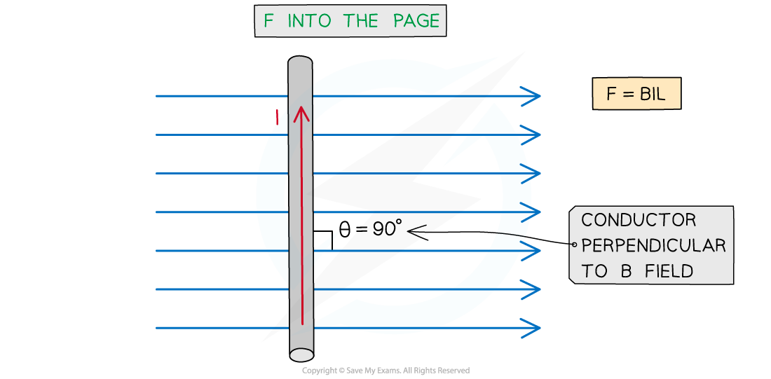
The magnitude of the force on a current-carrying conductor depends on the angle of the conductor to the external B field
A current-carrying conductor (e.g. a wire) will experience the maximum magnetic force if the current through it is perpendicular to the direction of the magnetic field lines
It experiences no force if it is parallel to magnetic field lines
The maximum force occurs when sin θ = 1
This means θ = 90° and the conductor is perpendicular to the B field
The equation for the magnetic force becomes:
The minimum force, i.e. F = 0 N, is when sin θ = 0°
This means θ = 0° and the conductor is parallel to the B field
It is important to note that a current-carrying conductor will experience no force if the current in the conductor is parallel to the field
This is because the F, B and I must be perpendicular to each other
Observing the Force on a Current-Carrying Conductor
The force due to a magnetic field can be observed by
placing a copper rod in a uniform magnetic field
connecting the copper rod to a circuit
When current is passed through the copper rod, it experiences a force
This causes it to accelerate in the direction of the force
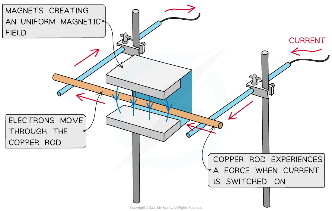
A copper rod moves within a magnetic field when current is passed through it
Worked Example
A current of 0.87 A flows in a wire of length 1.4 m placed at 30° to a magnetic field of flux density 80 mT.
Calculate the force on the wire.
Answer:
Step 1: Write down the known quantities
Magnetic flux density, B = 80 mT = 80 × 10−3 T
Current, I = 0.87 A
Length of wire, L = 1.4 m
Angle between the wire and the magnetic field, θ = 30°
Step 2: Write down the equation for force on a current-carrying conductor
Step 3: Substitute in values and calculate
F = (80 × 10-3) × (0.87) × (1.4) × sin(30) = 0.04872 = 0.049 N (2 s.f)
Examiner Tips and Tricks
Remember that the direction of current flow is the flow of positive charge (positive to negative), and this is in the opposite direction to the flow of electrons
Direction of Force on a Current-Carrying Conductor
When a current-carrying conductor is placed in a magnetic field, the force, B-field and current are all mutually perpendicular to each other
Their directions can be determined using Fleming’s left-hand rule
To use Fleming's left-hand rule, point the thumb, first finger and second finger at right angles to each other
The thumb points in the direction of motion or force F of the conductor
The first finger points in the direction of the applied magnetic field B
The second finger points in the direction of the flow of conventional current I (from positive to negative)
Fleming's Left-Hand Rule
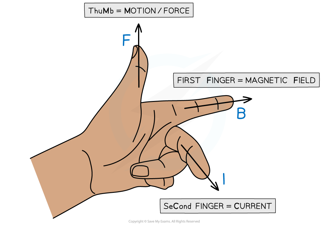
Fleming’s left-hand rule allows us to visualise the 3D arrangement of the force, magnetic field and current
Representing Magnetic Fields in 3D
When solving problems in three-dimensional space, the current, force or magnetic field could be directed into or out of the page
When the magnetic field is directed into or out of the page, the following symbols are used:
Dots (sometimes with a circle around them) represent the magnetic field directed out of the plane of the page
Crosses represent the magnetic field directed into the plane of the page
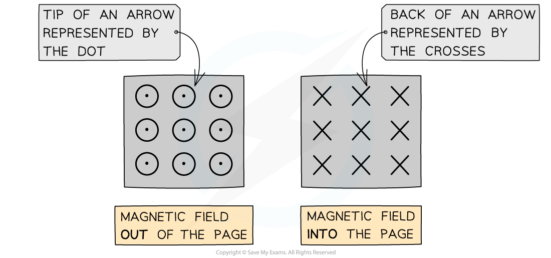
When the magnetic field is directed into or out of the page, we represent this with crosses or dots, respectively
The way to remember this is by imagining an arrow used in archery or darts:
If the arrow is approaching head-on, such as out of a page, only the very tip of the arrow can be seen (a dot)
When the arrow is receding away, such as into a page, only the cross of the feathers at the back can be seen (a cross)
Worked Example
State the direction of the current flowing in the wire in the diagram below.

Answer:
Using Fleming’s left-hand rule:
Magnetic field, B = into the page
Force, F = vertically downwards
Current, I = from right to left

Examiner Tips and Tricks
Don’t be afraid to use Fleming’s left-hand rule during an exam. Although, it is best to do it subtly in order not to give the answer away to other students!

You've read 0 of your 5 free revision notes this week
Sign up now. It’s free!
Did this page help you?
