Wave Phenomena (DP IB Physics: HL): Exam Questions

6 hours99 questions
1a3 marks

Outline what is meant by

(i) wavefront

[2]

(ii) ray.

[1]

1b4 marks

Draw, on the grid below, scale diagrams showing the wavefronts for 

(i) a plane wave with a wavelength of 1 cm

 [2]

(ii) a circular wave with a wavelength of 1 cm.

[2]

In your diagrams, show the direction of propagation with arrows.

8-1-ib-sl-sq1c-q-grid
2a2 marks

Outline what is meant by the principle of superposition.

2b1 mark

Two pulses travel toward one another as shown in the diagram.

4-3-3b-question-stem-sl-sq-easy-phy

Sketch the resultant displacement as the pulses superpose.

2c
Sme Calculator
1 mark

Two pulses travel in opposing directions as shown in the diagram. When the pulses meet, they superpose.

4-3-3c-question-stem-sl-sq-easy-phy

Draw the resultant peak as the pulses superpose.

2d
Sme Calculator
4 marks

Distinguish between the terms constructive interference and destructive interference.

3a1 mark

Monochromatic light from a single source is incident normally on two thin, parallel slits. The interference pattern observed on the screen is shown.

monochromatic-light-of-wavelength

State the order of the bright fringe at X.

3b
Sme Calculator
5 marks

The following data are available.

  • Wavelength = 600 nm

  • Distance to screen = 1.5 m

Calculate

(i) the average distance, in m, between two consecutive fringes

[1]

(ii) the separation of the slits

[2]

(iii) the angle between the centre of the pattern and X.

[2]

4a2 marks

State what is meant by: 

(i) the law of reflection

[1]

(ii) refraction.

[1]

4b2 marks

The diagram shows an incident ray perpendicular to the boundary between two media.

4-4-1b-question-stem-sl-sq-easy-phy

Complete the ray diagram by drawing the transmitted ray.

4c2 marks

The diagram shows the reflection of a light ray on a smooth surface.

4-4-1c-question-stem-sl-sq-easy-phy

On the ray diagram label: 

(i) the incident ray.

[1]

(ii) the reflected ray.

[1]

4d3 marks

The ray diagram shows an incident ray on a plane mirror.

4-4-1d-question-stem-sl-sq-easy-phy

Calculate the angle of reflection.

5a1 mark

Outline what is meant by critical angle.

5b
Sme Calculator
4 marks

A light ray is incident on an air-water boundary. The incident ray makes an angle of 40° with the normal.

4-4-2d-question-stem-sl-sq-easy-phy

The refractive index of air is 1.00, and the refractive index of water is 1.33.

Calculate

(i) the angle the refracted ray makes with the normal

(ii) the critical angle.

5c2 marks

Explain the change in the wavelength of the light at the air-water boundary.

6a1 mark

Outline what is meant by coherence.

6b
Sme Calculator
4 marks

The diagram shows two different waves from sources S1 and S2 meeting at point P.

4-4-3d-question-stem-sl-sq-easy-phy

For the waves meeting at point P: 

(i) determine the path difference.

[3]

(ii) state whether the interference will be constructive or destructive.

[1]

7a1 mark

Outline the condition for destructive interference.

7b1 mark

Some light can be described as monochromatic.

State what is meant by the term monochromatic.

7c
Sme Calculator
4 marks

The diagram shows the wave fronts emitted from two point sources S1 and S2

4-4-4c-question-stem-sl-sq-easy-phy

The waves meet at point P. 

(i) By considering the number of waves, determine the path difference.

[3]

(ii) State whether constructive or destructive interference would occur at point P.

[1]

7d2 marks

The diagram shows two sources of coherent light producing a double-slit interference pattern. 

4-4-4d-question-stem-sl-sq-easy-phy

State whether the interference is constructive or destructive at point: 

(i) A

[1]

(ii) B

[1]

8a2 marks

In a double-slit experiment, red laser light of wavelength 650 nm is incident on two slits, S1 and S2. The interference pattern is observed on a screen as shown. 

4-4-5b-question-stem-sl-sq-easy-phy

The separation of the slits is d = 0.2 mm, and the distance between the slits and the screen is D = 1.2 m.

Outline how the interference pattern observed on the screen would change if blue laser light were used instead.

8b
Sme Calculator
2 marks

Calculate the distance s between the fringes on the screen.

8c
Sme Calculator
2 marks

No bright fringe is observed on the screen at point X.

4-4-5d-question-stem-sl-sq-easy-phy

Explain why.

8d1 mark

One of the slits is covered so light can no longer pass through it.

Outline one change to the pattern observed on the screen.

9a3 marks

For the diffraction of light through a single slit, the following equation is used:

 theta space equals space lambda over b

The equation contains some assumptions about the set up of the equipment. 

(i) Outline why the slit width has to be has to be smaller than the wavelength of the incident light.

[1]

(ii) Explain why the screen must be placed a great distance away from the slit.

[2]

9b
Sme Calculator
2 marks

Monochromatic light of wavelength 450 nm is incident upon a single slit of width 1.3 µm.

Determine the angle of the first diffraction minimum.

9c
Sme Calculator
2 marks

Determine the angular width of the central maximum.

9d2 marks

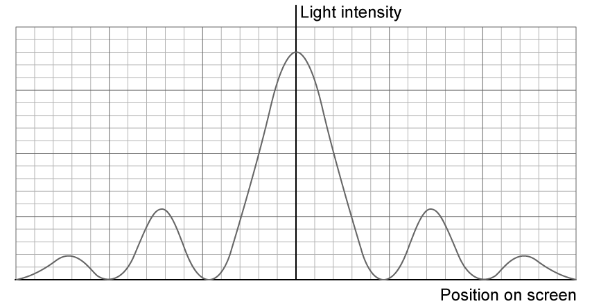
The light source used in the experiment is a blue laser.

The variation of light intensity with the position on the screen is shown for blue light.

diffraction-graph-1

The blue laser is replaced by a red laser.

Sketch, on the same axes, the variation of light intensity with the position on the screen for red light.

10a
Sme Calculator
3 marks

A group of students investigated single-slit diffraction using lasers of different wavelengths.

They use a slit of width 0.12 mm, but forget to note down the wavelength of the first laser. For this laser, the first diffraction minimum forms at an angle of 0.0050 rad to the central maximum.

(i) Calculate the wavelength of the incident light.

[2]

(ii) State the colour of the incident light.

[1]

10b3 marks

The students swap the laser for one that emits red light.

Explain the change to the pattern that the students will see on the screen.

10c
Sme Calculator
2 marks

The wavelength of the red laser light is 675 nm.

Calculate the angle between the first diffraction minimum and the central maximum for the red laser light.

10d3 marks

The students then decrease the slit width by half. 

Predict the effect this would have on the diffraction pattern.

11a
Sme Calculator
4 marks

The following graph shows the diffraction pattern for monochromatic light incident on a single slit.

9-2-esq-5a-q-stem-1

The wavelength of the light used is 4.5 × 10⁻⁷ m. Calculate the width of the slit.

11b
Sme Calculator
3 marks

The investigation from part (a) was repeated. The same light was used, but the slit width was doubled. 

On the same graph shown in part (a) sketch the resulting diffraction pattern for the new slit width.

11c
Sme Calculator
4 marks

Using the same light from parts (a) and (b), determine the slit width that would give the central maximum an angular width of 0.1 mrad.

11d
Sme Calculator
3 marks

Light with wavelength λ is incident upon a single slit of width b producing an angle of diffraction θ

Explain the change in the diffraction pattern if light with a wavelength lambda over 2 and a slit width b over 2 were used.

12a
Sme Calculator
2 marks

A diffraction grating has a width of 4 cm and contains 8000 slits.

Determine the number of slits per millimetre of the grating.

12b
Sme Calculator
2 marks

Determine the separation, in metres, between adjacent slits in the grating.

12c
Sme Calculator
4 marks

In an experiment, light of wavelength 650 nm is incident upon the diffraction grating. 

Calculate

(i) the angle at which the second order of diffraction is viewed

[2]

(ii) the greatest number of maxima that can be observed using this arrangement.

[2]

1a3 marks

Two microwave transmitters are placed 15 cm apart and connected to the same source. A receiver is placed 70 cm away and moved along a line parallel to the transmitter.

The microwaves emitted by the source have a frequency of 120 GHz. The receiver detects alternating maxima and minima of intensity.

Explain the formation of the intensity maxima and minima.

1b1 mark

Outline why the two sources must be coherent for the maxima and minima to be detected.

1c
Sme Calculator
3 marks

The receiver initially detects an intensity maximum at a point equidistant from the sources. Two minima, X1 and X2, are detected on either side of this maximum.

Calculate, in radians, the angular separation of X1 and X2.

2a
Sme Calculator
2 marks

A beam of monochromatic light is incident upon two slits. The distance between the slits is 0.4 mm.

q1a_wave-behaviour_ib-sl-physics-sq-medium

A series of bright and dark fringes appear on the screen. Explain how a bright fringe is formed.

2b
Sme Calculator
2 marks

Monochromatic light is incident on the double-slits, and the distance from the screen is 0.64 m. The distance between the bright fringes is 9.3 × 10⁻⁴ m.

Calculate the wavelength of the incident light.

2c2 marks

The wavelength of the incident light is halved, and the distance between the slits is doubled.

Outline the effect on the separation of the fringes of the interference pattern.

2d2 marks

One of the slits is covered so it emits no light.

Describe how this changes the pattern's appearance and the intensities observed on the screen.

3a
Sme Calculator
3 marks

Light is incident upon a piece of glass.

q2a_wave-behaviour_ib-sl-physics-sq-medium

The angle of incidence is less than that of the critical angle. The refractive index of the glass is 1.50.

Explain what is meant by the 'critical angle' and what will occur at angles that are above and below the critical angle.

3b
Sme Calculator
2 marks

The angle of incidence for this situation is 34°.

Determine the angle of refraction to the nearest degree.

3c
Sme Calculator
2 marks

The refracted light travels within the glass for 5 m.

Determine the time that the light will take to travel this distance in the glass.

3d
Sme Calculator
3 marks

The light continues within the glass until it strikes the side perpendicular to the original side of entry.

q2d_wave-behaviour_ib-sl-physics-sq-medium

Show that the light will not emerge from the side of the glass.

4a
Sme Calculator
2 marks

The diagram shows a cross-section through a step-index optical fibre.

QsFjbj7I_q3a_wave-behaviour_ib-sl-physics-sq-medium

Beam A is incident at the end of the optical fibre at an angle of 12.6° to the normal and refracts into the core at 6.89° to the normal.

Calculate the refractive index of the core.

4b
Sme Calculator
2 marks

Beam A travels through the air-core boundary and experiences total internal reflection.

On the diagram, show the path of this ray down the fibre and label the angle of reflection.

4c
Sme Calculator
2 marks

Beam B is incident at the same end of the fibre. It refracts through the air-core boundary and then refracts again when it hits the core-cladding boundary at an angle of 51.8°, traveling along the boundary.

Calculate the refractive index of the cladding.

4d
Sme Calculator
3 marks

A different step-index optical fibre is built with the same core as that in part (a) but with a different material used for the cladding.

The speed of light in the new cladding material is 1.54 × 10⁸ m s−1.

Explain why this new cladding material would not be suitable for sending signals through the step-index optical fibre. Use a calculation to support your answer.

5a4 marks

A beam of microwaves is incident normally on two very narrow slits, S1 and S2.

ib-9-3-sq-q1a-1

When a microwave receiver is initially placed at W, which is equidistant from the slits, an intensity maximum is observed. The receiver is then moved towards Z along a line parallel to the slits. Intensity maxima are also observed at X and Y, with one minimum between them. W, X and Y are consecutive maxima.

Explain the formation of

(i) the intensity maxima at W, X, and Y

[2]

(ii) the intensity minima between W, X, and Y.

[2]

5b
Sme Calculator
2 marks

The distance from S1 to Y is 1.482 m, and the distance from S2 to Y is 1.310 m.

Calculate the wavelength of the microwaves.

5c2 marks

On the axes, sketch the intensity variation for the points W, X and Y.

ib-9-3-sq-q1d
5d2 marks

The two narrow slits are replaced by two rectangular slits of finite size.

State one feature of the intensity pattern that will remain the same and one that will change.

6a
Sme Calculator
2 marks

A laboratory ultrasound transmitter emits ultrasonic waves of wavelength 0.7 cm through two slits. A receiver, moving along line AB, parallel to the line of the slits, detects regular rises and falls in the strength of the signal.

A student measures a distance of 0.39 m between the first and the fourth maxima in the signal when the receiver is 1.5 m from the slits.

_fKjM6aZ_q4a_wave-behaviour_ib-sl-physics-sq-medium

The ultrasound transmitter is a coherent source.

Explain what is meant by the term coherent source.

6b
Sme Calculator
4 marks

Explain why the receiver detects regular rises and falls in the strength of the signals as it moves along the line AB.

6c
Sme Calculator
3 marks

Calculate the distance between the two slits.

6d3 marks

One of the slits is now covered. No other changes are made to the experiment.

State and explain the difference between the observations made as the receiver is moved along AB before and after one of the slits is covered.

7a
Sme Calculator
3 marks

A beam of monochromatic light of frequency 2.44 × 10¹⁵ Hz is incident normally on a single rectangular slit.

A diffraction pattern is observed on a screen located 3.75 m from the slit. The distance on the screen from the central maximum to the first minimum is 0.25 cm.

Calculate the width of the slit. 

7b
Sme Calculator
4 marks

Three diffraction patterns, X, Y, and Z, are produced from three wavelengths of light, λ, 5λ and 10λ, passing through a single slit.

9-2-hl-sq-medium-q2c-diag

(i) State the wavelength of light that produced diffraction patterns X, Y, and Z. 

[2]

(ii) Explain which pattern has the highest intensity at the central maximum and state how to increase the intensity at the central maximum.

[2]

7c2 marks

The variation of intensity with position on the screen is shown.

Graph illustrating intensity distribution, with a central peak with the largest intensity and smaller peaks on either side, labelled 'Intensity' on the vertical and 'Position' on the horizontal.

The width of the slit is reduced.

Sketch, on the same axes, the variation of intensity with position on the screen for the narrower slit.

8a4 marks

Plane wavefronts of monochromatic light of wavelength λ are incident on a rectangular slit of width b. The light is brought to a focus after passing through the slit on a screen at a distance D from the slit as shown in the diagram below. 

The width of the slit is comparable to the wavelength of the light and b ≪ D. The point X on the screen is opposite the centre of the slit.  

9-2-hl-sq-medium-q3-diag

The variation of the intensity incident on the screen with angle θ is shown on the graph below.

9-2-hl-sq-medium-q3-graph

Outline why maximum and minimum values of intensity are observed on the screen at different values of theta.

8b
Sme Calculator
2 marks

In a single-slit diffraction experiment, the slit width is 0.030 mm and the wavelength of the light incident on the slit is 525 nm.

Calculate the angle of diffraction for the second maxima.

8c
Sme Calculator
3 marks

The single slit of width is replaced by three rectangular slits, also of width b. The intensity distribution of a single slit is shown by the dotted line.

9-2-hl-sq-medium-q3d

Sketch, on the axes, the intensity distribution for the three slits. 

9a
Sme Calculator
2 marks

A rectangular slit has width b and is comparable to the wavelength λ of plane wavefronts of monochromatic light incident upon it. After passing through the slit, the light is brought to a focus on a screen. 

9-2-hl-sq-medium-q5-diag

The diagram shows a line normal to the plane of the slit, drawn from the centre of the slit to the screen is labelled PQ. The points X and Y are the first points of minimum intensity as measured from point Q. 

The diagram also shows two rays of light incident on the screen at point X. Ray RX leaves one edge of the slit and ray PX leaves the centre of the slit. The angle φ is small. 

On the diagram, label two angles of diffraction.

9b
Sme Calculator
4 marks

Derive an expression, in terms of λ, for the path difference RT between the rays RX and RT.

9c
Sme Calculator
4 marks

Describe the changes in the experimental setup that would decrease the width of the central bright maximum.

9d
Sme Calculator
2 marks

In a certain demonstration of single-slit diffraction λ = 400 nm, b = 0.12 mm, and the screen is a long way from the slit. 

Calculate the angular width of the central maximum of the diffraction pattern on the screen.

10a
Sme Calculator
4 marks

Monochromatic light is incident normally on four, thin, parallel, rectangular slits. 

9-3-ib-hl-sq3-equip

The graph shows the variation with diffraction angle θ of the intensity of light I on a distant screen. 

9-3-ib-hl-sq3-graph

Iis the intensity of the light in the middle of the screen from one slit. Intensity is directly proportional to the square of amplitude A.

State the value of the light intensity in terms of I when θ = 0 and explain where this value comes from.

10b
Sme Calculator
2 marks

The width of each slit is 2.0 µm. 

Use the graph to estimate the wavelength of the light.

10c
Sme Calculator
3 marks

Use the graph to calculate the number of lines per metre on the diffraction grating. 

10d2 marks

The four slits are now changed for a grating where the number of slits becomes very large. The separation of the slits and their width stays the same.

State two changes to the graph that will appear as a result of this modification.

11a
Sme Calculator
3 marks

Monochromatic light is incident on a double-slit diffraction grating. After passing through the slits the light is brought to a focus on a screen. The intensity distribution of the light on the screen is shown in the diagram below. 

9-3-hl-sq-medium-q5-diag

The double-slit diffraction grating is now changed to a grating with many narrower slits, the same widths as the slits above. 

Sketch the new intensity pattern for the light between points C and D on the screen. 

11b
Sme Calculator
2 marks

The wavelength of the monochromatic light incident on the diffraction grating is 550 nm. The slit spacing of the diffraction grating is 1.34 × 10⁻⁶ m.

Calculate the angle between the two second-order maxima. 

11c
Sme Calculator
2 marks

Calculate the total number of orders of diffracted light that can be observed on the screen. 

11d
Sme Calculator
3 marks

Two sources of light now replace the light incident on the diffraction grating. One is the same as the wavelength of the previous source and the other has a slightly longer wavelength. 

Compare and contrast the new intensity pattern with the original. Comment on the intensity of the central maxima and the width of all maxima. 

1a
Sme Calculator
3 marks

Two coherent sources, A and B, which are in phase with each other, emit microwaves of wavelength 40.0 mm. The amplitude of waves from source B is twice that of source A. 

A detector is placed at the point P where it is 0.93 m from A and 1.19 m from B. The centre axis is normal and a bisector to the straight line joining A and B. 

4-3-ib-sl-hard-sqs-q2a-question

With reference to the phase of the microwaves, deduce the magnitude of the detected signal at P and explain your reasoning.

1b
Sme Calculator
5 marks

Deduce, with suitable calculations, how the detected signal varies as the detector is moved from P to O.

1c
Sme Calculator
2 marks

The source B is altered such that it emits waves that are 180° out of phase with source A. 

Deduce the type of interference that now occurs at point P and explain your reasoning. 

2a
Sme Calculator
2 marks

A ray of light passes from air into a glass prism.

4-4-ib-sl-hard-sqs-q2a-question

As the light ray passes through the prism, it emerges back into the air.

Calculate the critical angle from the glass to the air.

2b
Sme Calculator
3 marks

The prism is rotated and one side is coated with a film of transparent gel. A ray of light strikes the prism, at an angle of incidence of 38°, and continues through the glass to strike the glass–gel boundary at the critical angle.

4-4-ib-sl-hard-sqs-q2c-question

Calculate the refractive index of the gel.

2c
Sme Calculator
2 marks

A ray of light now strikes the prism at an angle of incidence which means that it now refracts straight through the gel at the glass–gel boundary.

Without calculation, explain how the critical angle for the glass–gel boundary differs from the critical angle for the gel–air boundary.

3a
Sme Calculator
4 marks

The diagram shows a cross–section through an optical fibre used in an endoscope. The critical angle is 7% lower than the 75º angle to the normal at the core–cladding boundary. The refractive index of the cladding is 1.4.

4-4-ib-sl-hard-sqs-q4b-question

Calculate the angle of incidence theta subscript i at the air–core boundary.

3b
Sme Calculator
3 marks

Complete the graph to show how the refractive index changes with radial distance along the line ABCD in Figure 2.

4-4-ib-sl-hard-sqs-q4c-question
4a
Sme Calculator
3 marks

The diagram below shows an arrangement for observing the interference pattern produced by laser light passing through two narrow slits S1 and S2.

9-3-hl-sq-medium-q2a-diag

The distance S1S2 is d, and the distance between the double slit and the screen is D where D d, so angles θ and ϕ are small. M is the midpoint of S1S2 and it is observed that there is a bright fringe at point A on the screen, a distance fn from point O on the screen. Light from S1 travels a distance S2Y further to point A than light from S1.

The wavelength of light from the laser is 650 nm, and the angular separation of the bright fringes on the screen is 5.00 × 10⁻⁴ rad.

Calculate the distance between the two slits.

4b
Sme Calculator
3 marks

A bright fringe is observed at A. 

(i) Explain the conditions required in the paths of the rays coming from Sand S2 to obtain this bright fringe. 

[2]

(ii) Determine an equation for the distance S2Y in terms of n and lambda.

[1]

4c
Sme Calculator
4 marks

Determine an expression for

(i) theta in terms of n, lambda and d

[2]

(ii) phi in terms of D and space f subscript n.

[2]

5a
Sme Calculator
5 marks

Some students in a lab are performing a single-slit diffraction investigation. They have a green laser but they do not know the exact wavelength of the light. 

Describe which measurements the students can take and how they can use them to calculate the wavelength.

5b
Sme Calculator
5 marks

The students recorded the following information:

Green laser

Repeat 1

Repeat 2

Repeat 3

Repeat 4

Repeat 5

Distance from slit to screen, D / m

3.11

3.12

3.11

3.11

3.12

Slit width, b / mm

0.14 

0.10 

0.71 

0.11 

0.13 

Width of central maximum, w / cm

2.8

2.7

2.9

2.9

2.6

Calculate the wavelength of the laser and give its fractional uncertainty.

6a2 marks

Single-slit diffraction patterns provide evidence for light as a wave. 

The images below show the diffraction of light around a small circular object. 

pfjRXAk7_9-2-hsq-4a-q-stem

Suggest how the images provide evidence for light as a wave.

6b
Sme Calculator
4 marks

The image shows a diffraction pattern from a single rectangular slit.

ePOUNIFP_9-2-hsq-3b-q-stem

Sketch the diffraction pattern if the slit width was 20% smaller.

nj~PYy0A_9-2-hsq-3b-q-stem-empty-box-
7a
Sme Calculator
3 marks

Monochromatic light from a single source is incident on two thin parallel slits. 

9-3-ib-hl-hsq1-a-q

The following data are available: 

  • Distance from slits to screen = 4.5 m

  • Wavelength = 690 nm

  • Slit separation = 0.13 mm

The intensity, of the light on the screen from each slit separately is I0

9-3-ib-hl-hsq1-a-q2

Sketch, on the axis, a graph to show variation with distance on the screen against the intensity of light detected on the screen for this arrangement.

7b
Sme Calculator
4 marks

State and explain the changes that will occur to the diffraction pattern when the number of slits is increased from two to three.

8a2 marks

Monochromatic light of wavelength lambda is normally incident on a diffraction grating. The light waves are diffracted through an angle theta to form a first-order diffraction maximum.

The diagram shows two adjacent slits of the diffraction grating labelled A and B. Point C is also labelled.

9-3-ib-hl-hsq2a-q

The separation of adjacent slits is d.

Show that for the first-order diffraction maximum lambda space equals space d space sin space theta

8b
Sme Calculator
4 marks

Monochromatic light of wavelength 545 nm is normally incident on a diffraction grating. The diffraction maxima are observed on a screen, and their angle theta to the central beam is determined.

The graph shows the variation of sin space theta with the order n of the maximum. The central order corresponds to n = 0.

9-4-ib-hl-hsq2b-q

Determine a mean value for the number of slits per millimetre of the grating.

8c
Sme Calculator
3 marks

A beam of light containing all the wavelengths in the range 500 nm to 600 nm is incident normally on the diffraction grating.

Determine the largest order of the diffraction pattern in which all the wavelengths in the incident beam are present.