Diffraction Gratings (DP IB Physics) : Revision Note
The Diffraction Grating
A diffraction grating is a piece of optical equipment that also creates a diffraction pattern when light is passed through it
Diffraction gratings diffract:
Monochromatic light into bright and dark fringes
White light into its different wavelength components
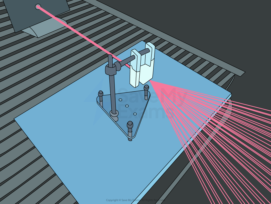
A laser beam is diffracted through a diffraction grating
A diffraction grating consists of a large number of very thin, equally spaced parallel slits carved into a glass plate
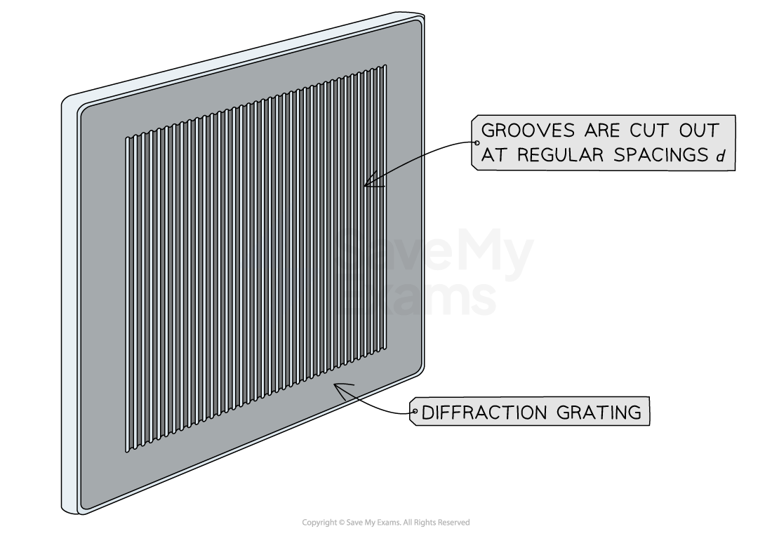
A diffraction grating consists of many parallel equally spaced slits cut into the glass plate
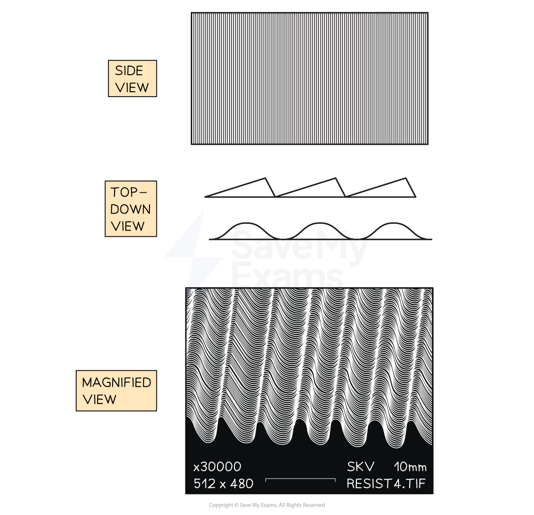
When you look closely at a diffraction grating you can see the curved shape of the slits
The Diffraction Grating Equation
Diffraction gratings are useful because they create a sharper pattern than a double slit
This means their bright fringes are narrower and brighter while their dark regions are wider and darker
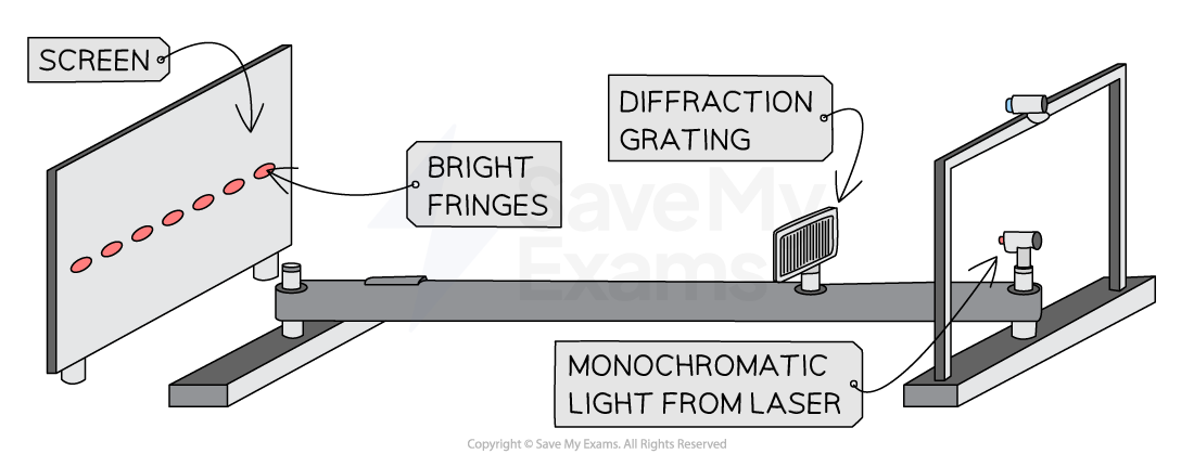
A diffraction grating is used to produce narrow bright fringes when laser light is diffracted through it
Just like for single and double-slit diffraction the regions where constructive interference occurs are also the regions of maximum intensity
Their location can be calculated using the diffraction grating equation

Where:
n is the order of the maxima, the number of the maxima away from the central (n = 0)
d is the distance between the slits on the grating (m)
θ is the angle of diffraction of the light of order n from the normal as it leaves the diffraction grating (°)
λ is the wavelength of the light from the source (m)
Number of Slits
Increasing the number of slits increases the number and intensity of the maxima in the intensity pattern
This is because more slits means more diffraction and more constructive interference
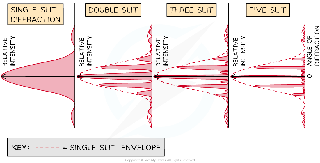
The combined diffraction and interference patterns, called the intensity pattern, for light interfering through different numbers of slits. The maximum intensity increases as the number of slits increases, so the intensity in each graph is relative to that number of slits only
Slit Spacing
Diffraction gratings come in different sizes
The sizes are determined by the number of lines per millimetre (lines / mm) or lines per m
This is represented by the symbol N
d can be calculated from N using the equation
If N is given in terms of lines per mm then d will be in mm
If N is given in terms of lines per m then d will be in m

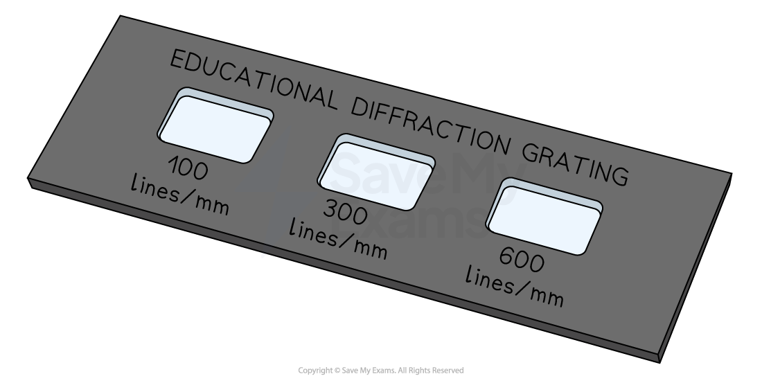
Diffraction gratings come in different sizes according to the number of lines per mm
Angular Separation
The angular separation of each maxima is calculated by rearranging the grating equation to make θ the subject
The angle θ is taken from the centre meaning the higher orders of n are at greater angles of diffraction
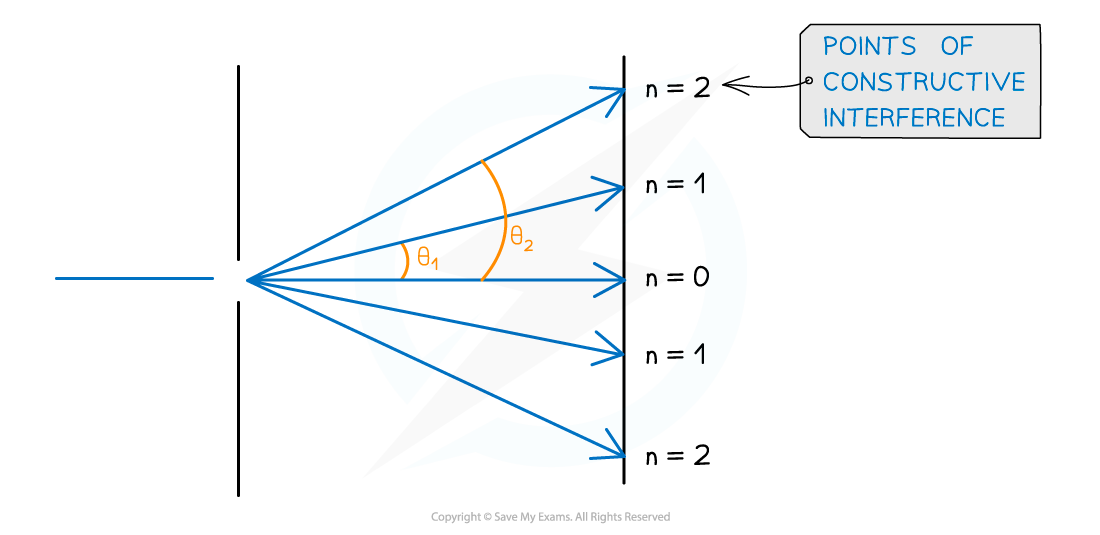
Angular separation increases as the order of maxima increases
The angular separation between two angles is found by subtracting the smaller angle from the larger one
The angular separation between the first and second maxima at n1 and n2 is θ2 – θ1
Orders of Maxima
The maximum angle of diffraction with which maxima can be seen is when the beam is at right angles to the diffraction grating
This means θ = 90o and sin θ = 1
The highest order of maxima visible is therefore calculated by the equation:

Since n is an integer number of maxima, if the value obtained is a decimal it must be rounded down to determine the highest-order visible
E.g If n is calculated as 2.7 then n = 2 is the highest-order visible
The Diffraction of White Light
A source of white light diffracted through a diffraction grating will produce the following diffraction pattern:
It is different to that produced by a double or single slit
The first-order spectrum n = 1 is used for analysis
The central maximum is a very thin bright strip because each wavelength interferes here constructively
It is surrounded by wide dark destructive interference fringes
All other maxima are composed of a spectrum
Separate diffraction patterns can be observed for each wavelength of light
The shortest wavelength (violet / blue) would appear nearest to the central maximum because it is diffracted the least
The longest wavelength (red) would appear furthest from the central maximum because it is diffracted the most
The colours look blurry and further away from the central maximum, the fringe spacing gets so small that the spectra eventually merge without any space between them
As the maxima move further away from the central maximum, the wavelengths of blue observed decrease and the wavelengths of red observed increase
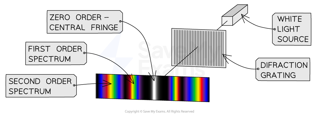
The diffraction pattern of white light diffracted through a diffraction grating
Worked Example
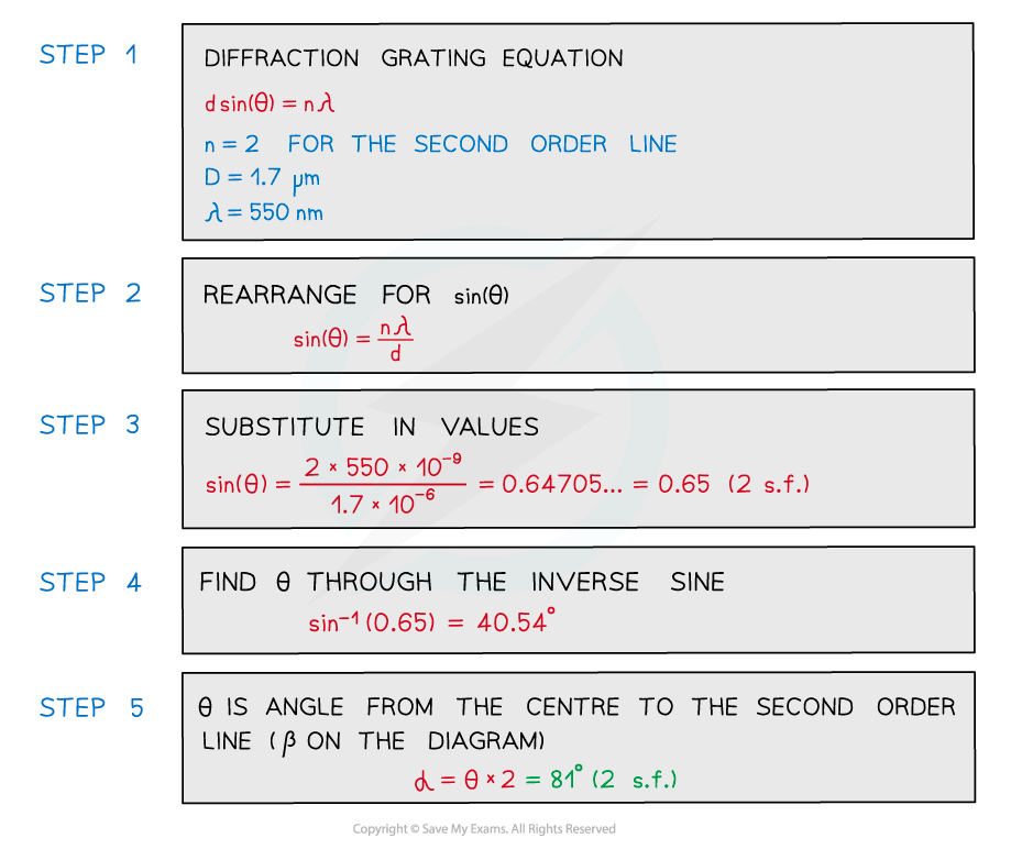
An experiment was set up to investigate light passing through a diffraction grating with a slit spacing of 1.7 µm. The fringe pattern was observed on a screen. The wavelength of the light is 550 nm.
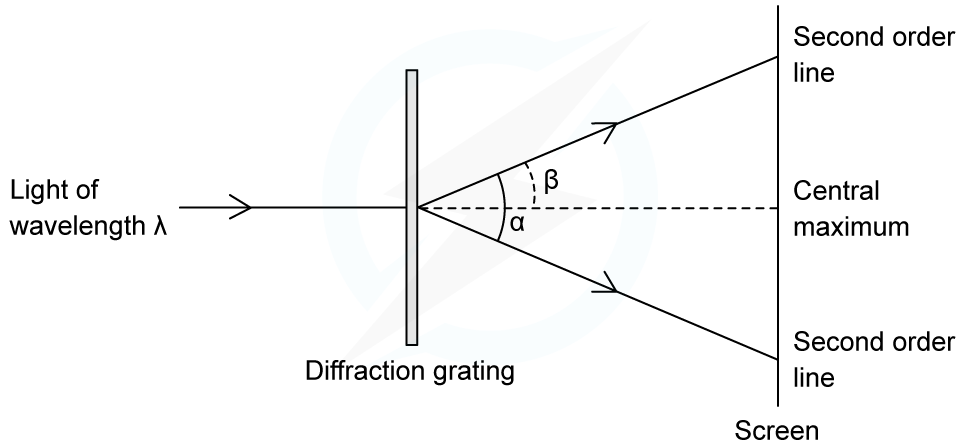
Calculate the angle α between the two second-order lines.
Answer:
Examiner Tips and Tricks
Take care that the angle θ is the correct angle taken from the centre and not the angle taken between two orders of maxima.

You've read 0 of your 5 free revision notes this week
Unlock more, it's free!
Did this page help you?
