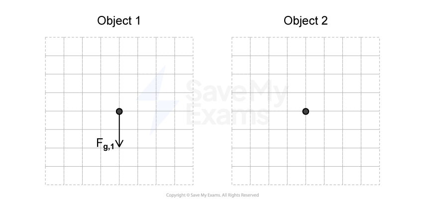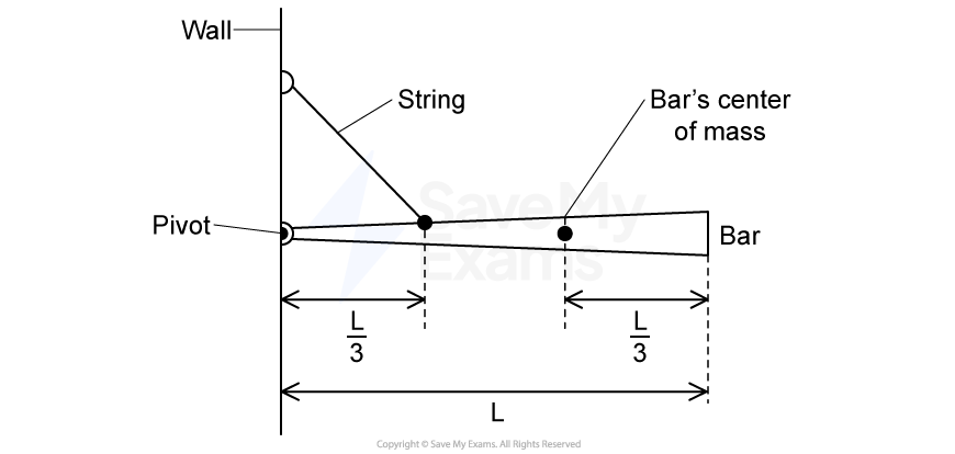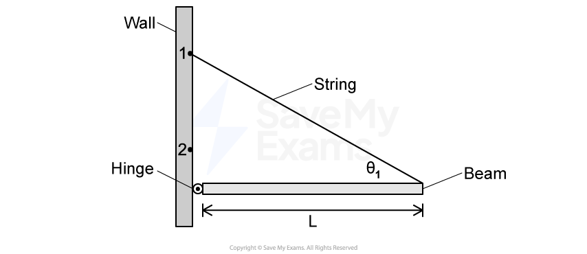
Figure 1
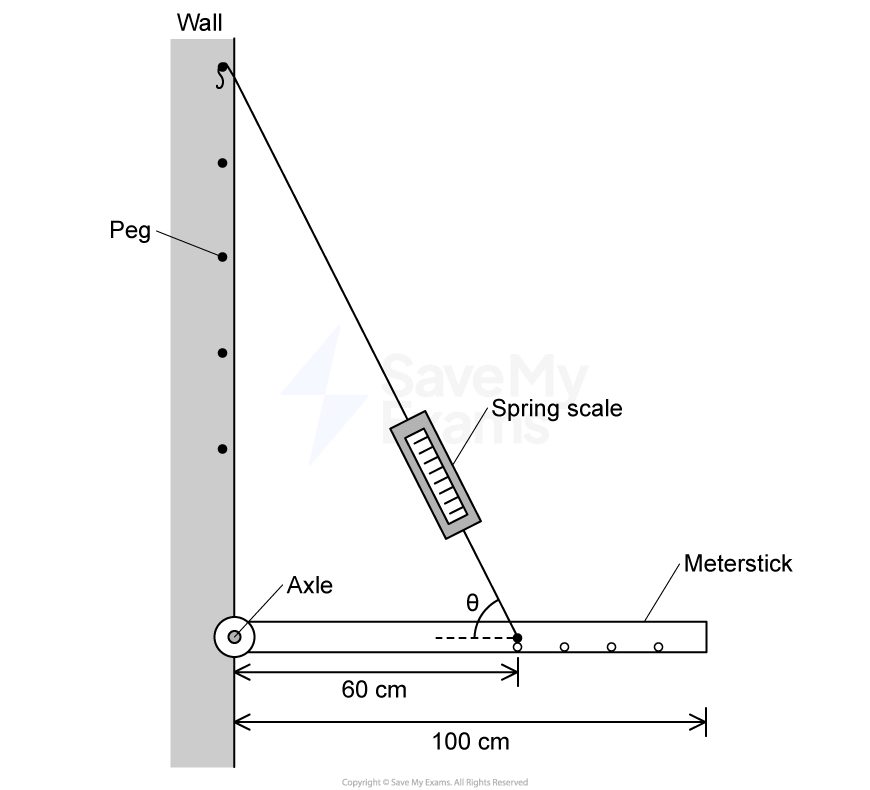
The left end of a uniform beam of mass ![]() and length
and length ![]() is attached to a wall by a hinge, as shown in Figure 1. One end of a string with negligible mass is attached to the right end of the beam. The other end of the string is attached to the wall above the hinge at Point 1. The beam remains horizontal. The hinge exerts a force on the beam of magnitude
is attached to a wall by a hinge, as shown in Figure 1. One end of a string with negligible mass is attached to the right end of the beam. The other end of the string is attached to the wall above the hinge at Point 1. The beam remains horizontal. The hinge exerts a force on the beam of magnitude ![]() , and the angle between the beam and the string is
, and the angle between the beam and the string is ![]() .
.
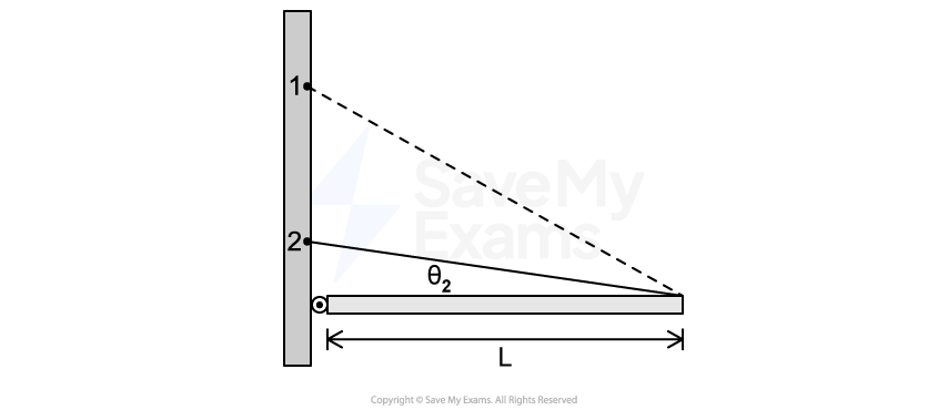
Figure 2
The string is then attached lower on the wall, at Point 2, and the beam remains horizontal, as shown in Figure 2. The angle between the beam and the string is ![]() . The dashed line represents the string shown in Figure 1.
. The dashed line represents the string shown in Figure 1.
The magnitude of the tension in the string shown in Figure 1 is ![]() . The magnitude of the tension in the string shown in Figure 2 is
. The magnitude of the tension in the string shown in Figure 2 is ![]() .
.
Indicate whether ![]() is greater than, less than, or equal to
is greater than, less than, or equal to ![]() .
.
⎽⎽⎽⎽⎽⎽⎽⎽⎽⎽ ![]() ⎽⎽⎽⎽⎽⎽⎽⎽⎽⎽
⎽⎽⎽⎽⎽⎽⎽⎽⎽⎽ ![]() ⎽⎽⎽⎽⎽⎽⎽⎽⎽⎽
⎽⎽⎽⎽⎽⎽⎽⎽⎽⎽ ![]()
Briefly justify your answer, using qualitative reasoning beyond referencing equations.
Starting with Newton’s second law in rotational form, derive an expression for the magnitude of the tension in the string. Express your answer in terms of ![]() ,
, ![]() , and physical constants, as appropriate. Begin your derivation by writing a fundamental physics principle or an equation from the reference booklet.
, and physical constants, as appropriate. Begin your derivation by writing a fundamental physics principle or an equation from the reference booklet.
Does the equation you derived in part b) agree with your qualitative reasoning from part a)? Justify why or why not.
Did this page help you?