Materials (OCR A Level Physics): Structured Questions

Exam code: H556

47 mins17 questions
1a
1 mark

Explain what is meant by the ultimate tensile strength of a material.

1b
6 marks

A footbridge is supported by a number of metal cables of the same length.

Each cable has uniform cross-section and diameter 4.20 mm as shown in Fig. 16.1.

309tQAau_fig-16-1-h556-01-qp-june-2019-ocr-a-level-physics

Fig. 16.1 (not to scale)

A group of engineers investigate how the extension x varies with applied force F for one of the cables.

The results of the investigation are shown in Fig. 16.2.

fig-16-2-h556-01-qp-june-2019-ocr-a-level-physics

Fig. 16.2

The cable breaks when the force is 2.2 kN.

i) Describe how a suitable measuring device may have been used by the engineers to demonstrate that the cable had uniform cross-section.

[2]

ii) State any value of F when the cable behaves

  1. elastically

    F = ............................................ kN

  2. plastically.

F = ............................................ kN

[2]

iii) Use Fig. 16.2 to determine the force constant k in Nm–1 of the cable.                       

k = ............................................... Nm–1  [2]

1c
2 marks

Determine the breaking stress σ of the cable.

Assume that the cross-sectional area of the cable remains constant during the test.

σ = .................................... Pa [2]

1d
2 marks

Explain why the work done on the cable when its extension changes from 3.0 mm to 4.0 mm is greater than when its extension changes from 1.0 mm to 2.0 mm.

2a
3 marks

A student investigates the properties of a metal wire.

The wire is suspended from a fixed support and loads are added to the free end.

The wire has an original length of 2.40 m and a diameter of 0.38 mm.

Fig. 16.1 shows the variation of the extension x of the wire with the applied force F.

Fig. 16.1

Line graph titled "Force vs Extension," showing a linear increase from 0 to 20 N as extension increases from 0 to 5 mm.

(i) Define the term ultimate tensile stress.

[1]

(ii) Describe a procedure the student could use to measure the extension of the wire accurately.

[2]

2b
2 marks

Use Fig. 16.1 to calculate the work done on the wire when the tensile force is increased from 0 N to 20 N.

2c
3 marks

Use Fig. 16.1 to calculate the Young modulus E of the metal.

2d
1 mark

The diameter of the wire was measured using a micrometer screw gauge.

Describe how the student should use the micrometer to reduce the uncertainty in the measurement of the diameter.

3a
4 marks

A light spring with an unstretched length of 1.5 cm is hung from a fixed point. An object of weight 4.0 N is hung from the other end of the spring. Fig. 4.1 shows the length of the spring when the object is in equilibrium.

Diagram of a spring hanging from a fixed support with a block labelled 4.0 N attached to its lower end. Two dashed lines mark the top and the bottom of the spring, and the length between them is labelled 10.5 cm.

Fig. 4.1

The object is then pulled vertically downwards and is no longer in its equilibrium position. This is shown in Fig. 4.2.

Diagram of the same spring and 4.0 N block after the block has been pulled downwards, so the spring is longer than in Fig. 4.1. No length is marked.

Fig. 4.2

The change in elastic potential energy ∆E between the spring in Fig. 4.1 and Fig. 4.2 is 0.25 J.

Calculate the length of the spring in Fig. 4.2.

length = .................................................. m

3b
3 marks

The object is released from its position shown in Fig. 4.2.

Show that its initial acceleration is upwards with a magnitude of 5 m s−2.

3c
6 marks

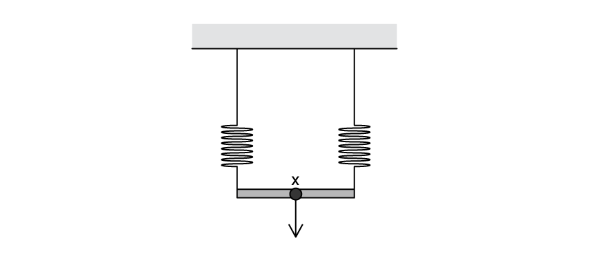
A student now replaces the spring with two identical springs arranged in parallel so that both springs support the load under static conditions. The arrangement is shown in Fig. 4.3. Point X is a hook where a mass can be attached.

Diagram of two identical springs hanging side by side from a fixed support. Their lower ends are joined by a horizontal bar. A hook labelled X is at the centre of the bar, with an arrow pointing vertically downwards from it.

Fig. 4.3

Describe how the student could carry out an experiment to determine the effective spring constant of the parallel arrangement.

In your answer, you should:

  • describe how the apparatus is set up

  • explain what measurements are taken and how they are used

  • explain how the data are processed to obtain the effective spring constant

  • describe precautions taken to improve the reliability and accuracy of the results