Faraday's & Lenz's Laws (OCR A Level Physics): Revision Note
Exam code: H556
Faraday's & Lenz's Laws
Faraday's Law
Faraday's Law connects the rate of change of flux linkage with induced e.m.f
It is defined in words as:
The magnitude of the induced e.m.f. is directly proportional to the rate of change of magnetic flux linkage
Faraday's Law as an equation is defined as:
Where:
ε = induced e.m.f (V)
Δ(Nɸ) = change in flux linkage (Wb turns)
Δt = time interval (s)
Lenz's Law
Lenz’s Law is used to predict the direction of an induced e.m.f. in a coil or wire
Lenz's Law is summarised below:
The induced e.m.f. is set up in a direction to produce effects that oppose the change causing it
Lenz's Law can be experimentally verified using:
A bar magnet
A coil of wire
A sensitive ammeter

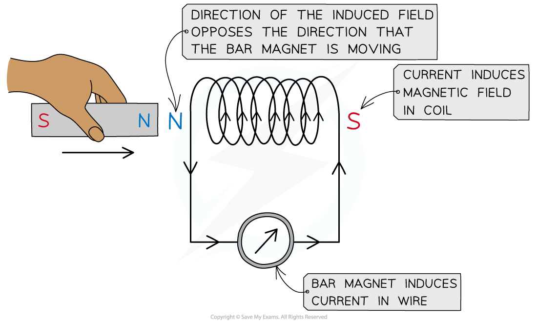
Lenz’s law can be verified using a coil connected in series with a sensitive ammeter and a bar magnet
A known pole (either north or south) of a bar magnet is pushed into the coil
This induces an e.m.f. in the coil
The induced e.m.f. drives a current (because it is a complete circuit)
Lenz's Law dictates:
The direction of the e.m.f, and hence the current, must be set up to oppose the incoming magnet
Since a north pole approaches the coil face, the e.m.f. must be set up to create an induced north pole
This is because two north poles will repel each other
The direction of the current is therefore as shown in the image above
The direction of current can be verified using the right hand grip rule
Fingers curl around the coil in the direction of current and the thumb points along the direction of the flux lines, from north to south
Therefore, the current flows in an anti-clockwise direction in the image shown
This induces a north pole, opposing the incoming magnet

Unlock more, it's free!
Did this page help you?