Practical Skills (Edexcel A Level Physics): Revision Note
Exam code: 9PH0

Written by: Katie M
Updated on
Practical Skills
Using Equipment
Good practical skills involves choosing the right equipment
Knowing how to use it for a physics experiment is crucial
When using measuring instruments, it is important to be aware of what each division on a scale represents
This is known as the resolution
A list of common apparatus is shown below:

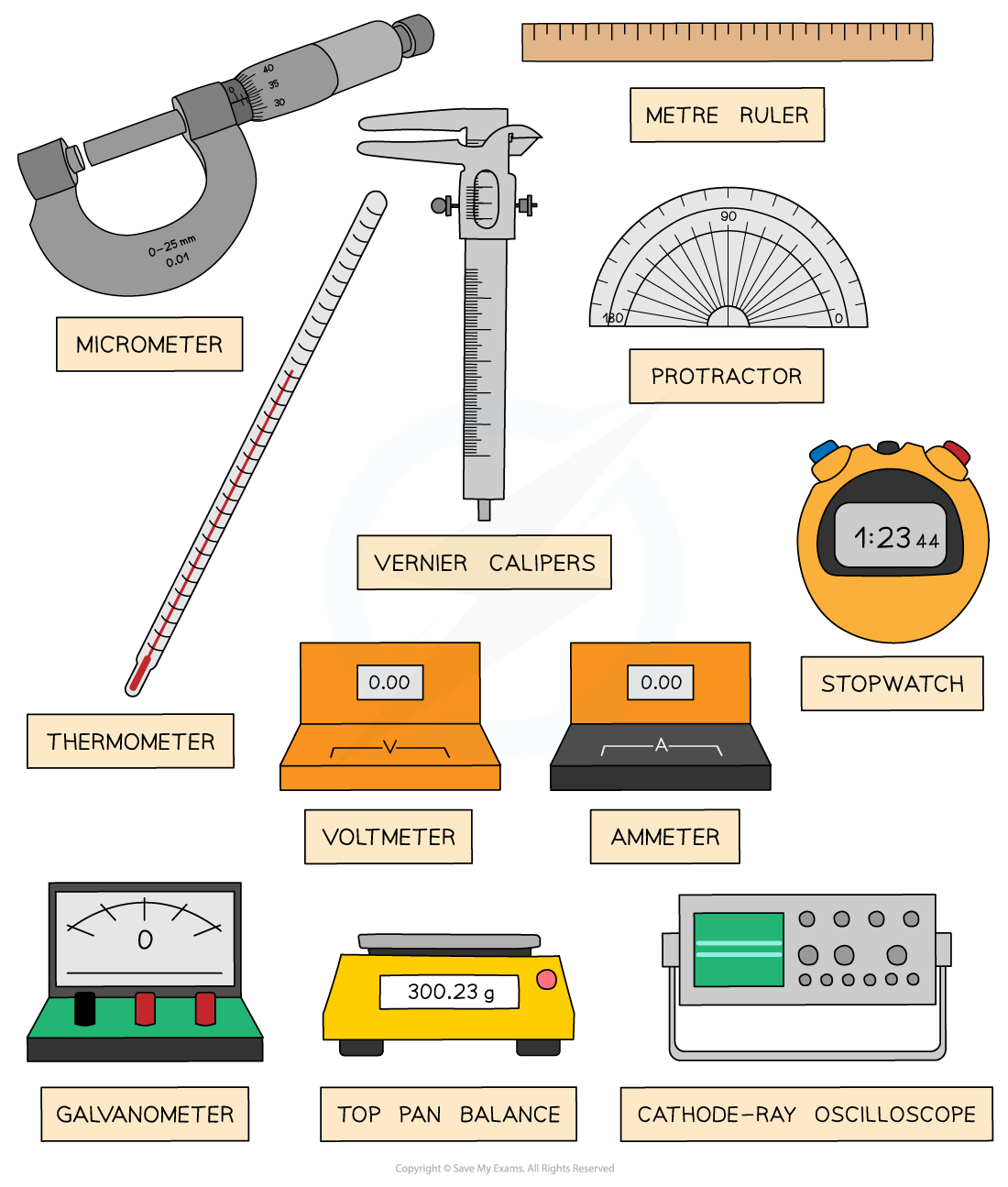
A selection of apparatus commonly used in physics experiments
Types of Display
Scientific instruments can be digital or analogue
Analogue
Analogue scientific instruments transfer information through electric pulses of varying amplitude
This means they cannot be read easily by a computer
Analogue instruments are cheaper but they have lower accuracy and resolution
They are also more sensitive, which can make it difficult to read fluctuating values
An analogue display normally involves a pointer which indicates a value depending on its position or angle on the scale

Analogue meter
The measurements taken on this analogue ammeter are restricted over a range e.g. 0 - 10 A and a resolution of 1 A
Analogue meters are subject to zero errors
This means the marker must be double-checked before each reading. If it is not at zero, then the value but be subtracted from all the measurements
They are also subject to parallax error
Always read the meter from a position directly perpendicular to the scale
A potentiometer is an example of a sensitive analogue meter
Digital
Digital scientific instruments translate information into binary (0 or 1) format which can then be read and analysed by a computer
They are more expensive but have greater accuracy and resolution than analogue instruments
Digital displays show the measured values as digits
They’re easy to use because they give a specific value and are capable of displaying more precise values

Digital meter
The measurements taken on this digital ammeter have a much wider range and a resolution of 0.01 A
Digital meters are also subject to zero error
Make sure the reading is zero before starting an experiment, or subtract the “zero” value from the end results
Most digital meters have an auto-range function, this means it can show very low or very high values depending on the readings
This saves time selecting an instrument with the correct range and precision for your experiment
A digital multi-meter is an example of a digital meter
Reading Distances
Reading distances using calipers or micrometers will be expected for the practical examination
Micrometer Screw Gauge
A micrometer, or a micrometer screw gauge, is a tool used for measuring small widths, thicknesses or diameters
For example, the diameter of a copper wire
It has a resolution of 0.01 mm
The micrometer is made up of two scales:
The main scale - this is on the sleeve (sometimes called the barrel)
The thimble scale - this is a rotating scale on the thimble

Components of a micrometer
By rotating the rachet, the spindle and anvil are clamped around the object being measured
This should be tight enough so the object does not fall out but not so tight that is deformed
Never tighten the spindle using the barrel, only using the ratchet. This will reduce the chances of overtightening and zero errors
The value measured from the micrometer is read where the thimble scale aligns with the main scale
This should always be recorded to 2 decimal places (eg. 1.40 mm not just 1.4 mm)

The micrometer reading is read when the thimble scale aligns with the main scale
Vernier Calipers
Vernier calipers are another distance measuring tool that uses a sliding vernier scale
They can also be used to measure diameters and thicknesses, just like the micrometer
However, they can also measure the length of small objects such as a screw or the depth of a hole
Vernier calipers generally have a resolution of 0.1 mm, however, some are as small as 0.02 mm - 0.05 mm
The calipers are made up of two scales:
The main scale
The vernier scale
The two upper or lower jaws are clamped around the object
The sliding vernier scale will follow this and can be held in place using the locking screw
The lower jaws measure internally - they measure the size of an object inside the jaws
The upper jaws measure externally - they measure the size of an object either side the jaws

Components of a vernier caliper
The value read from the caliper when the vernier scale aligns with the main scale
This should always be recorded to at least 1 decimal place (eg. 12.1 mm not just 12 mm)

The vernier caliper reading is read when the vernier scale aligns with the main scale
In general, the micrometer has a smaller measuring range than a vernier caliper
However, the micrometer has a better accuracy (due to better resolution)
The vernier caliper is quicker to use, whilst the micrometer involves rotating the thimble
Therefore, to take many measurements, a caliper would be easier to use
Signal Generators & Oscilloscopes
Signal generators and oscilloscopes are commonly used in practicals to visualise waves
Signal Generator
A signal generator is an electronic test instrument used to create repeating or non-repeating waveforms
They can be adjusted for different shapes and amplitudes
These are often used for designing and repairing electronic devices, to check they are working as expected
Signal generators are used to create signals to then show on oscilloscopes

A signal generator can be used to create signals for a CRO
Cathode-Ray Oscilloscope
A Cathode-Ray Oscilloscope (CRO) is a laboratory instrument used to display, measure and analyse waveforms of electrical circuits
It can therefore be used as an a.c and d.c voltmeter

A cathode-ray oscilloscope displays the signal generated by the signal generator
An a.c voltage on an oscilloscope is represented as a transverse wave
Therefore you can determine its frequency, time period and peak voltage
A d.c voltage on an oscilloscope is represented as a horizontal line at the relevant voltage
The x-axis is the time and the y-axis is the voltage (or y-gain)

Diagram of Cathode-Ray Oscilloscope display showing wavelength and time-base setting
The period of the wave can be determined from the time-base
This is how many seconds each division represents measured commonly in s div-1 or s cm-
C.R.O Controls for an A.C waveform
Time-base
When the time-base is switched off, only a vertical line on the voltage-gain axis is seen with its relevant amplitude
When the time-base is switched on, a wave will appear across the whole screen and the time period can be measured
This control has units of time cm-1 or time div-1 and has a range of 100 ms – 1 μs per cm, or division
Voltage-gain (sensitivity)
This controls the vertical deflection, or amplitude, of the wave
The peak voltage (V0) is the maximum vertical displacement measured from the time axis
The peak-to-peak voltage is the vertical displacement between the minimum and maximum values of voltage
When the voltage-gain is switched off, only a horizontal line on the time axis will be seen
This control has units of volts cm-1 or volts div-1
C.R.O Controls for a D.C waveform
For a d.c waveform, only a horizontal line is displayed at the relevant voltage
The time-base settings are irrelevant since there is no time period
The voltage-gain setting is relevant since this is used to read the value of the d.c voltage


Examples of an alternating and direct voltage on a CRO with and without the time base
Timing
A stopwatch or light gates are common physics instruments used for measuring time
For example, the time taken for a ball to fall a certain distance

A stopwatch is used to measure the time interval between the clap and when the sound is heard
The disadvantage of keeping time manually using a stopwatch is there will be a large error in the reading
This is caused by:
Human reaction time (on average, about 0.25 s)
The mechanism of the stopwatch (older stopwatches may have a slight delay)
Accidentally pressing the start or stop button too many times
Consistently starting the stopwatch too late or too early
Therefore, repeat readings are very important for experiments that require timekeeping
Light Gate
A light gate is a digital switch-type sensor also used in time experiments
They consist of an infrared transmitter and receiver between the 'gate'
When this signal is obstructed by an object, a timer can either be started or stopped depending on its configuration
If the distance between two light gates is known, the time interval between an object passes through both gates can then be used to measure its speed using the equation:
speed = distance ÷ time
This is assuming the object is not accelerating

The first light gate starts a timer, and the second stops the timer when the flag passes between them. This is used to determine the speed of the object
A light gate is much more accurate than a stopwatch, as it removes the errors caused by human reaction time
They can also be connected to a digital timer or datalogger, which then output the time in which the signals are obstructed for data analysis
Computer Modelling & Data Loggers
Computing modelling and data loggers are essential in all scientific experiments for obtaining and analysing reliable results
Data Loggers
Data loggers are a tool that allows for the quick and efficient gathering of data
The information contained within a data logger can be inputted into a computer and formatted into a table
After this is done the computer is able to calculate the average and plot graphs using the data and calculate gradients, quicker and more accurately than humans
They are electronic devices that automatically monitor and record environmental parameters over time such as temperature, pressure, voltage or current
It contains multiple sensors to receive the information and a computer chip to store it

A data logger measuring and displaying temperature using a probe
The benefits of using data loggers and ICT (information and communication technology) include:
Readings are taken with higher degrees of accuracy
Reduction of human error (eg. human reaction times, subjectiveness)
Readings can be taken over a long period of time eg. hourly readings of temperature over many days
Readings can be taken in a very short period of time, which would be too quick for humans to see a difference
Reduction in safety risks with extreme conditions such as measuring the temperature of boiling water
Computer Modelling
Computer modelling is commonly done in conjunction with devices such as a data logger
Modelling is about processing the data collected from a physics experiment into software or a spreadsheet
Graphs and charts can be generated from a table of values
These can then be exported to a scientific report
One of the benefits of these computer programs is that time can be sped up to predict the future outcome of an experiment

Computer modelling uses a computer and sensors to analyse and display data
Examiner Tips and Tricks
You must be familiar with all the different uses of apparatus and techniques. The apparatus to use depends on the measurement you are trying to make. For example, the diameter of a piece of hair is so small (on the order of 0.01 mm) it is best to measure with a micrometer instead of a ruler. However, the length of a piece of string would be better measured with a ruler, since it will be a few centimetres long.
Make sure to practice reading values from a micrometer or vernier scale ready for your practical paper. These can be easy marks when done correctly!

Unlock more, it's free!
Join the 100,000+ Students that ❤️ Save My Exams
the (exam) results speak for themselves:

Was this revision note helpful?