A long straight wire passes through a piece of card. There is a current in the wire, as shown in Fig. 1.1a.

Fig. 1.1a
The current in the wire produces a magnetic field around the wire.
(i) Fig. 1.1b shows the view of the card from above. On Fig. 1.1b, draw the magnetic field around the wire.
Show the direction of the magnetic field by drawing an arrow on each field line.

Fig. 1.1b
[2]
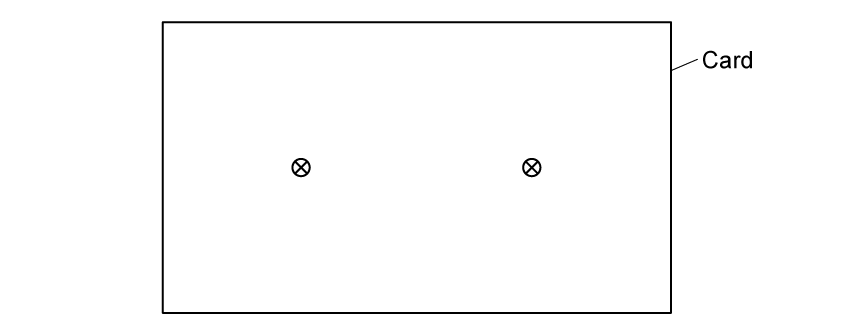
(ii) Two identical wires with the same current pass through a different piece of card.
On Fig. 1.1c, draw the magnetic field around the wires.

Fig. 1.1c
[2]
The current-carrying wire is placed in a uniform magnetic field.
(i) State the equation, and define all the variables, for the force on a current-carrying wire in a uniform magnetic field at different angles.
[2]
(ii) Describe how the wire should be placed to experience
1. the maximum force due to the magnetic field
2. no force due to the magnetic field.
[2]
A current-carrying conductor placed at right angles to a uniform magnetic field which has a magnetic flux density of 15 × 10−3 T.
The conductor has a length of 1.2 m and a current of 1.5 A flowing through it.
Calculate the magnetic force acting on the conductor.
The conductor is then rotated so that it is at an angle of 30° to the magnetic field.
Calculate the new force acting on the conductor.
Did this page help you?


