Two Source Interference (Cambridge (CIE) A Level Physics): Revision Note
Exam code: 9702
Demonstrating two source interference
Two source interference can be demonstrated using
water waves in a ripple tank
sound
light
microwaves
Using water waves
Two-source interference in can be demonstrated in water using ripple tanks
A curved line represents each wavefront (peak or trough)
The diagram below shows the wavefronts from two point sources e.g. dropping two pebbles near to each other in a pond
Wavefront interference
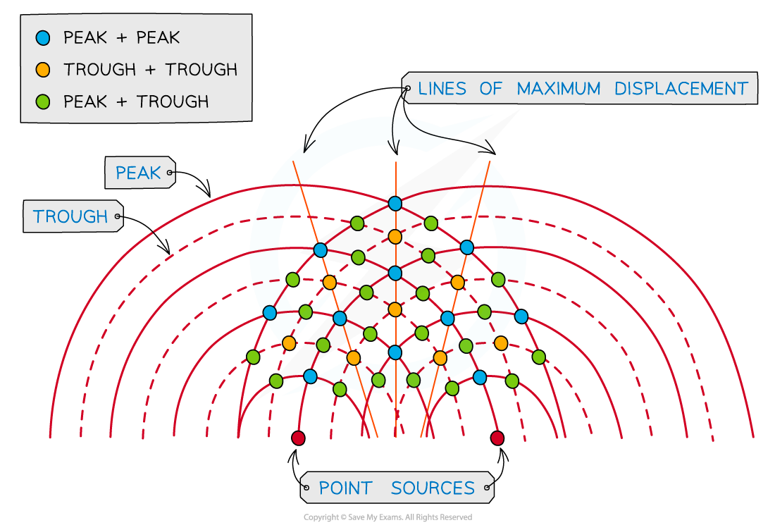
At the blue dot where the peak of two waves meet, constructive interference occurs. At the yellow dot where two troughs meet, constructive interference also occurs. Constructive interference occurs along the lines of maximum displacement. At the green dot, where a peak and a trough meet, destructive interference occurs
The lines of maximum displacement occur when all the peaks and troughs line up with those on another wave
On a wavefront diagram, it is possible to count the number of wavelengths to determine whether constructive or destructive interference occurs at a certain point
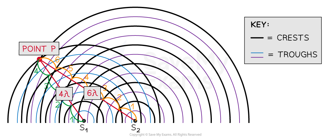
At point P the waves from S1 and S2 have a path difference of a whole number of wavelengths, resulting in constructive interference
At point P, the number of crests from:
Source S1 = 4λ
Source S2 = 6λ
So the path difference at P is 6λ – 4λ = 2λ
This is a whole number of wavelengths, hence, constructive interference occurs at point P
Using sound waves
Two-source interference can be demonstrated with two speakers emitting a coherent sound
Sound wave interference
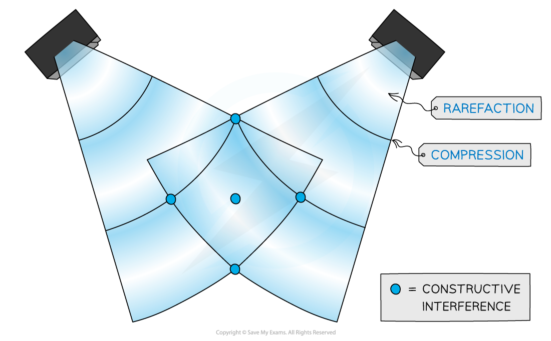
Sound wave interference from two speakers
Sound waves are longitudinal waves made up of compressions and rarefactions
Constructive interference occurs when the compressions and rarefactions from each wave line up and the sound appears louder
Destructive interference occurs when a compression from one wave lines up with a rarefaction from the other and vice versa. The two waves cancel each other out, so zero sound is heard.
This is the technology used in noise-cancelling headphones
Using microwaves
Two-source interference for microwaves (and other electromagnetic waves) can be detected with a moveable microwave detector
Microwave interference experiment
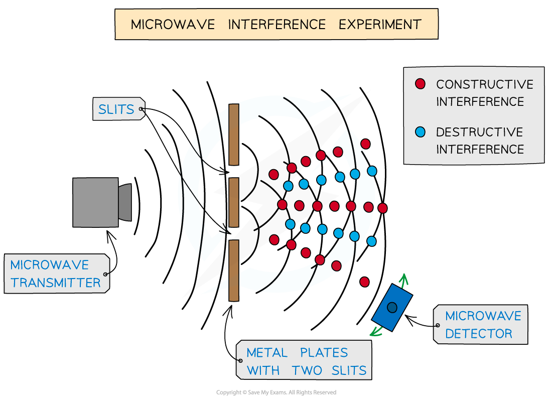
Microwave interference experiment
The detector picks up a maximum amplitude or intensity in regions of constructive interference
The detector picks up a minimum or zero amplitude, so no signal in regions of destructive interference
Using light waves
Lasers are the ideal piece of equipment to analyse diffraction and intensity patterns
The diffraction pattern produced by a laser on a screen is made up of:
Areas of constructive interference - the bright strips or fringes
Areas of destructive interference - the dark fringes
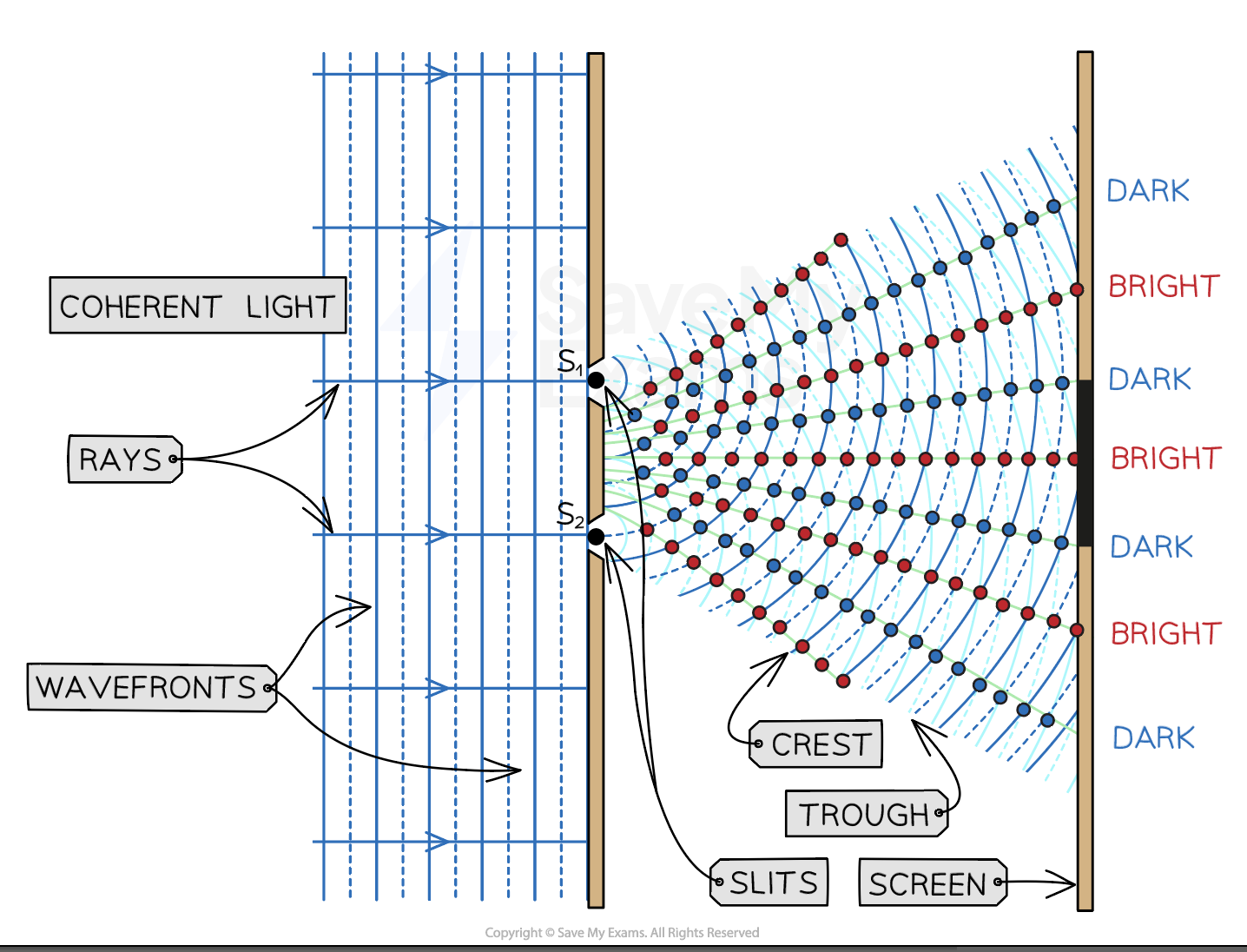
The constructive and destructive interference of laser light through a double slit creates bright and dark strips called fringes on a screen placed far away
Two source interference fringes
For two-source interference fringes to be observed, the sources of the wave must be:
Coherent (constant phase difference)
Monochromatic (single wavelength)
A laser is an example of a coherent monochromatic light source
Other sources of light, such as a filament bulb or a sodium lamp, are non-coherent, so they produce white light
A laser beam
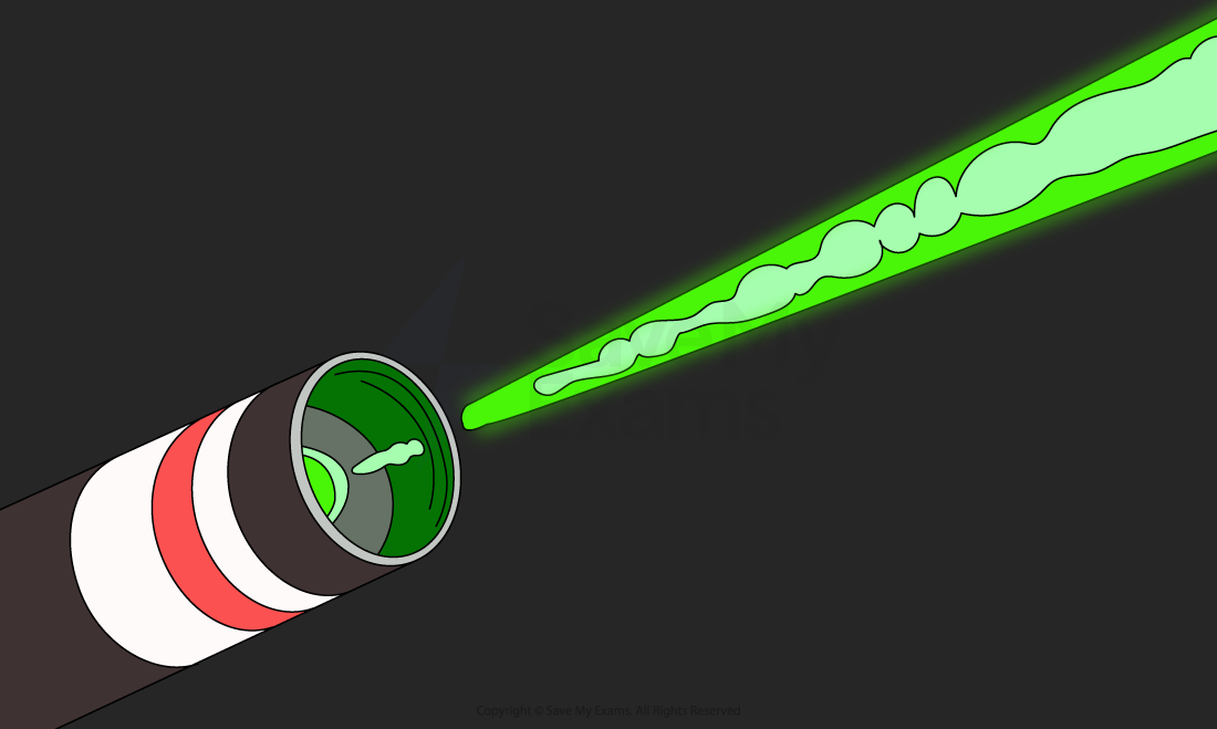
A laser produces a beam of coherent monochromatic light
When two waves interfere, the resultant wave depends on the phase difference between the two waves
Phase difference is proportional to the path difference between the waves which can be written in terms of the wavelength λ of the wave
As seen from the diagram below, the wave from slit S2 has to travel slightly further than that from S1 to reach the same point on the screen.
The difference in distance is the path difference
Path difference for constructive and destructive interference
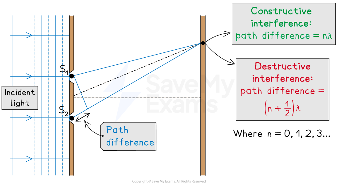
Path difference for constructive and destructive interference is determined by wavelength
Remember, the conditions for Constructive and destructive interference:
For constructive interference (or maxima), the difference in wavelengths will be an integer number of whole wavelengths
For destructive interference (or minima) it will be an integer number of whole wavelengths plus a half wavelength
An example of the orders of maxima is shown below:
n is the order of the maxima/minima since there is usually more than one of these produced by the interference pattern
Double slit interference pattern
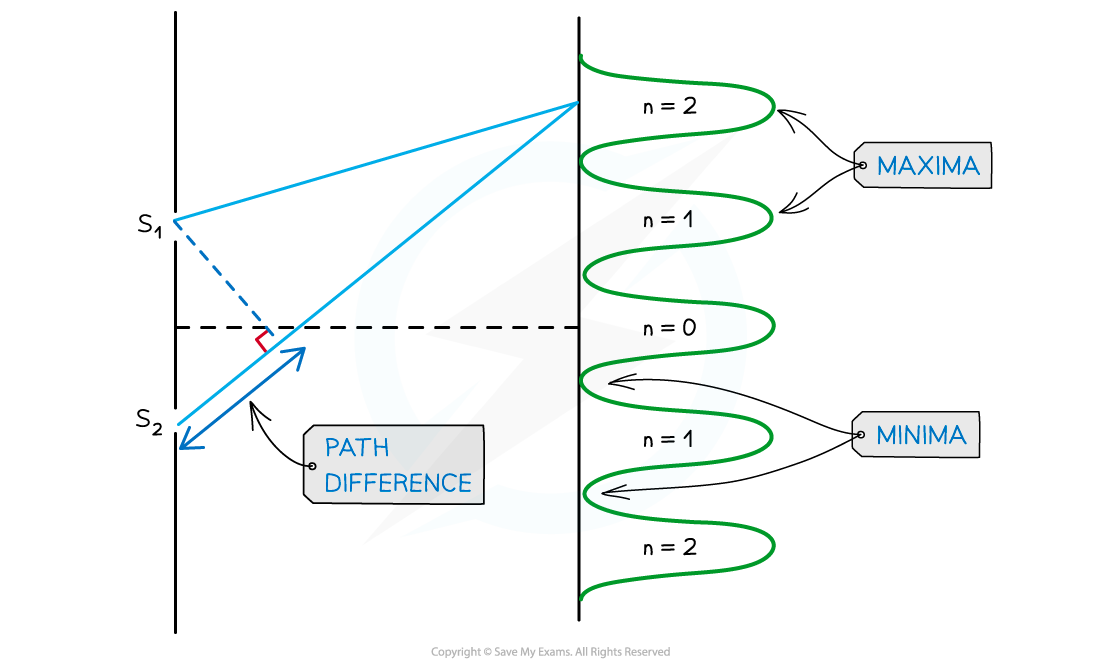
Interference pattern of light waves shown with orders of maxima
n = 0 is taken from the middle, n = 1 is one either side and so on
Worked Example
Two coherent sources of sound waves S1 and S2 are situated 65 cm apart in air as shown below.

The two sources vibrate in phase but have different amplitudes of vibration. A microphone M is situated 150 cm from S1 along the line normal to S1 and S2.
The microphone detects maxima and minima of the intensity of the sound. The wavelength of the sound from S1 to S2 is decreased by increasing the frequency.
Determine which orders of maxima are detected at M as the wavelength is increased from 3.5 cm to 12.5 cm.
Answer:
Step 1: Calculate the path difference
Using Pythagoras' theorem, the distance from source S2 to the microphone is:
Therefore, the path difference between the sources and the microphone is:
Path difference =
Step 2: State the path difference for constructive interference
Path difference = nλ
n = 0, 1, 2, 3...
Step 3: Determine the wavelength
Path difference = nλ = 13 cm
Only orders n = 2 and n = 3 are within the wavelength range of 3.5 cm to 12.5 cm
Therefore, n = 2 and n = 3 are the orders where the maxima are detected
Examiner Tips and Tricks
The path difference is more specifically how much longer, or shorter, one path is than the other. In other words, the difference in the distances. Make sure not to confuse this with the distance between the two paths.

Unlock more, it's free!
Did this page help you?