Rotational Dynamics (AQA A Level Physics)

Exam Questions

42 mins5 questions
1a
Sme Calculator
3 marks

A gymnast dismounts from an exercise in which he swings on a high bar. The gymnast rotates in the air before landing.

Figure 1 shows the gymnast in three positions during the dismount.

Figure 1
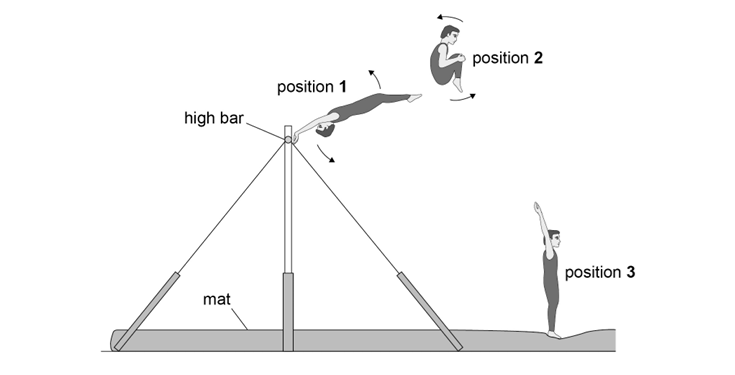
Diagram of a gymnast performing a routine on a high bar. Positions 1, 2, and 3 show different stages from swinging to landing on a mat.

The arrows show the direction of rotation of the gymnast.

In position 1 the gymnast has just let go of the bar. His body is fully extended.

Position 2 shows the rotating gymnast a short time later. His knees have been brought close to his chest into a ‘tuck’.

Position 3 is at the end of the dismount as the gymnast lands on the mat. His body is once again fully extended.

Explain why the moment of inertia about the axis of rotation decreases when his knees are moved towards his chest.

Go on to explain the effect this has on his angular speed.

1b
Sme Calculator
1 mark

Table 1 gives some data about the gymnast in position 1 and in position 2.

Table 1

Position

Moment of inertia / kg m2

Angular speed / rad s−1

1

13.5

omega

2

4.1

14.2

Calculate the angular speed omega of the gymnast in position 1.

1c
Sme Calculator
2 marks

The gymnast stays in the tuck for 1.2 s.

Determine the number of complete rotations performed by the gymnast when in the tuck during the dismount.

1d
Sme Calculator
4 marks

The gymnast repeats the exercise. The height of the bar remains unchanged.

State and explain two actions the gymnast can take to complete more rotations during the dismount.

Did this page help you?

2a
Sme Calculator
2 marks

There is an analogy between quantities in rotational and translational dynamics.

Complete Table 1, stating in words the quantities in rotational dynamics that are analogous to force and mass in translational dynamics.

Table 1

Translational dynamics

Rotational dynamics

force

mass

2b
Sme Calculator
1 mark

Figure 1 shows a side view of the jib of a tower crane. The load is supported by a trolley which can move along the jib. The jib consists of all the parts of the crane above the bearing, but excluding the trolley and load.

Figure 1

Diagram of a tower crane showing the axis of rotation, 35m jib, bearing, trolley, and load, illustrating the crane's structure and function.

The moment of inertia of the jib about the axis of rotation = 2.6 × 10⁷ kg m2

Mass of trolley and load = 2.2 × 10³ kg

The load is at a distance of 35 m from the axis of rotation.

Show that the total moment of inertia of the jib, and the trolley and load, about the axis of rotation is about 3 × 10⁷ kg m2.

2c
Sme Calculator
2 marks

Figure 2 shows the variation of angular speed of the jib as it turns through an angle of 4.7 rad (270°) in a total time of 95 s. The trolley and load remain at a distance of 35 m from the axis.

Figure 2

Graph of angular speed versus time with a triangular shape, peaking at ωmax. Not to scale. Peaks at 30 to 50 seconds with 95 seconds total duration.

Calculate the maximum angular speed omega subscript m a x end subscript of the jib.

2d
Sme Calculator
3 marks

At time X in Figure 2 the motor that is driving the jib is disengaged. A constant braking torque is then applied to bring the jib to a standstill from its maximum angular speed.

The crane driver repeats the movement of the jib with the same load at 35 m from the axis of rotation. Up to time X the motion is the same as before. From time X the trolley is driven at a steady speed away from the axis as the jib continues to rotate until the jib comes to a standstill.

Assume the braking torque remains the same as before.

Discuss how the motion of the trolley affects the time taken for the jib to come to a standstill.

Did this page help you?

3a
Sme Calculator
3 marks

Figure 2 shows a yo-yo made of two discs separated by a cylindrical axle. Thin string is wrapped tightly around the axle.

Figure 2

Diagram showing edge and front views of a wheel with string attached. Labels include 'axle', 'r', 'v', and 'ω', indicating rotation and direction.

Initially both the free end A of the string and the yo-yo are held stationary.

With A remaining stationary, the yo-yo is now released so that it falls vertically. As the yo-yo falls, the string unwinds from the axle so that the yo-yo spins about its centre of mass.

The linear velocity v of the centre of mass of the falling yo-yo is related to the angular velocity omega by v space equals space r omega where space r is the radius of the axle.

The yo-yo accelerates uniformly as it falls from rest. The string remains taut and has negligible thickness.

  • mass of yo-yo = 9.2 × 10⁻² kg

  • radius of axle = 5.0 × 10⁻³ m

  • moment of inertia of yo-yo about axis X-X = 8.6 × 10⁻⁵ kg m2

When the yo-yo has fallen a distance of 0.50 m, its linear velocity is V.

Calculate V by considering the energy transfers that occur during the fall.

3b
Sme Calculator
3 marks

The yo-yo falls further until all the string is unwound. The yo-yo then ‘sleeps’. This means the yo-yo continues to rotate in a loose loop of string as shown in Figure 3.

Figure 3

Diagram of a yo-yo, showing a rotational arrow from the top to the side, indicating clockwise motion.

The string applies a constant frictional torque of 8.3 × 10⁻⁴ N m to the axle.

The angular velocity of the yo-yo at the start of the sleep is 145 rad s−1.

Determine, in rad, the total angle turned through by the yo-yo during the first 10 s of sleeping.

Did this page help you?

4a
Sme Calculator
2 marks

One equation used in translational dynamics is:

force = mass × acceleration

State in words the equivalent equation used in rotational dynamics.

4b
Sme Calculator
2 marks

Figure 1 shows two identical uniform plates A and B. The axis of rotation of each plate is shown.

Figure 1

Two plates labeled A and B, each with a vertical axis of rotation marked on the left end of A and through the centre of mass of B.

State and explain which plate has the greater moment of inertia about its axis of rotation.

4c
Sme Calculator
2 marks

An electric motor drives a machine that punches out plates from a long strip of sheet metal. The motor runs continuously and is fitted with a flywheel.

Figure 2 shows how the angular velocity omega of the flywheel varies with time t.

Figure 2

Graph showing how the angular velocity ω of the flywheel varies with time t. Between points A and B the angular velocity rapidly decreases from ωA to ωB, and gradually increases back up to ωA at point C. The cycle repeats twice more.

Table 1 describes the sequence for the machine after it has been brought up to speed omega subscript A.

Table 1

A

The punching operation starts.

A to B

The flywheel transfers some of its energy during the punching operation.

B to C

The flywheel is again brought up to speed omega subscript A by the motor.

C

The next punching operation starts.

A new flywheel with a greater moment of inertia is fitted in place of the original flywheel. The motor torque is constant and the same as before.

Sketch on Figure 2 a graph showing how the angular velocity varies with time for the machine fitted with the new flywheel.

Assume that:

  • the punching operation starts at the same angular speed omega subscript A

  • the same quantity of energy is transferred when punching the metal sheet.

4d
Sme Calculator
1 mark

Explain one difference between your graph and the original graph.

Did this page help you?

5a
Sme Calculator
2 marks

Figure 3 shows a heavy stone grinding wheel used for sharpening tools.

Figure 3

Diagram of a heavy stone grinding wheel showing a wheel, crank, axle, connecting link, and pedal, with arrows indicating the wheel rotates in an anticlockwise direction as the pedal is pushed downwards.

The pedal is connected to the axle of the wheel by a connecting link and crank.

The operator pushes the pedal downwards to accelerate the wheel from rest.

The wheel begins to rotate in the direction shown.

Explain why the torque applied to the axle varies as the operator pushes downwards on the pedal.

5b
Sme Calculator
2 marks

The wheel is rotating at a high angular speed. The operator is told not to use the pedal to stop the rotation of the wheel suddenly.

Explain, with reference to angular impulse, why a sudden stop is likely to damage the mechanism.

5c
Sme Calculator
2 marks

The connecting link breaks. At this instant the angular speed of the wheel is 13.8 rad s−1.

It takes 15.0 s for the wheel to come to rest.

The frictional torque acting at the axle bearings is 0.77 N m and is constant for all speeds.

Calculate the moment of inertia of the wheel.

5d
Sme Calculator
2 marks

The arrangement is modified as shown in Figure 4. The pedal, connecting link and crank are removed and the grinding wheel is driven by an electric motor.

Figure 4

Diagram of a grinding wheel setup showing a tool applied to the wheel, powered by an electric motor below, with force F on the tool indicated by an arrow.

Figure 4 also shows a tool being sharpened by pressing it on the edge of the rotating wheel.

The tool applies a tangential force F on the wheel.

A torque of 3.10 N m is needed at the axle to drive the wheel at constant angular speed while the tool is being sharpened.

frictional torque at the axle bearings = 0.77 N m

radius of wheel = 0.24 m

Calculate F.

5e
Sme Calculator
3 marks

Three motors E, F and G were available to drive the wheel in Figure 4.

Figure 5 shows how the torque T varies with angular speed omega for each motor.

Figure 5

Three line graphs show torque vs angular velocity for motors E, F, and G, each with different, negative slopes. 
Graph E starts at T = 0.84 N m and ends at ω0 = 240 rad/s
Graph F starts at T = 1.04 N m and ends at ω0 = 300 rad/s
Graph G starts at T = 1.28 N m and ends at ω0 = 180 rad/s

The no-load speed omega subscript 0 is the angular speed of a motor when the torque applied is zero.

The maximum power of each motor is developed at about 0.5 omega subscript 0.

The required output power of the motor when a tool is being sharpened is 52 W.

The required output power of the chosen motor should be about 2 over 3 of its maximum power.

Deduce which motor E, F or G was chosen for this application.

Did this page help you?