State the purpose of the magnetic field in a magnetic resonance scanner.
Describe the role of the radio frequency pulses in a magnetic resonance scanner.
Did this page help you?
Exam code: 7408
State the purpose of the magnetic field in a magnetic resonance scanner.
How did you do?
Describe the role of the radio frequency pulses in a magnetic resonance scanner.
How did you do?
Did this page help you?
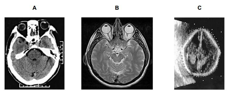
Figure 1 shows scanned images of three different human heads.
Figure 1

Each image used one of the following scanning techniques:
magnetic resonance (MR)
CT
ultrasound
PET
Identify the scanning technique used for each image.
Go on to explain how the features of each image enabled you to identify the type of scan.
How did you do?
Did this page help you?
State what is meant by the specific acoustic impedance of a medium.
How did you do?
Table 1 shows the density and speed of ultrasound in soft tissue, in bone and in air.
Table 1
| density / kg m−3 | speed of ultrasound / m s−1 |
air | 1.29 | 330 |
soft tissue | 1060 | 1540 |
bone | 1600 | 4000 |
Using the data in Table 1, calculate
(i) the acoustic impedance of air
[1]
(ii) the acoustic impedance of soft tissue
[1]
(iii) the acoustic impedance of bone
[1]
How did you do?
The intensity reflection coefficient α for two media is given by
Where Z1 and Z2 are the specific acoustic impedances of the two media.
Explain how this equation can be used to predict if ultrasound will be reflected or transmitted at the boundary between two materials.
How did you do?
Did this page help you?
Figure 1 shows an ultrasound transducer used to perform medical scans.
Figure 1

Ultrasound of frequency 1.0 MHz is used to scan a person’s liver. Estimate the resolution of the scan in mm.
speed of sound in liver tissue = 1600 m s−1
How did you do?
Ultrasound travels from a transducer through the chest wall to an air pocket inside the lung. From the air pocket, the ultrasound is then incident on lung tissue.
Calculate the percentage of the incident ultrasound intensity transmitted into the lung tissue.
speed of sound in lung tissue = 1580 m s−1
density of lung tissue = 1075 kg m−3
speed of sound in air = 330 m s−1
density of air = 1.3 kg m−3
How did you do?
Discuss whether an ultrasound scan would be suitable to investigate a tumour inside a lung.
How did you do?
Did this page help you?
Most modern ultrasound transducers are made from the piezoelectric material lead zirconate titanate (PZT).
Figure 1 shows the effect on the structure of a crystal of PZT when an alternating potential difference is applied across it.
Figure 1

i) Describe what happens at a molecular level when an alternating potential difference is applied across a PZT transducer to generate ultrasound.
You may draw on Figure 1 to help with your answer.
[4]
ii) Describe the conditions that will enable maximum energy conversion into ultrasound to occur.
[2]
How did you do?
An eye can be imaged using either an A-scan or a B-scan ultrasound. Figure 2 shows the position of a piezoelectric transducer being used during an A-scan of an eye.
Figure 2

i) Explain how an A-scan could be used to measure the thickness of a patient’s eye lens. You may draw on Fig. 1.2 to help with your answer.
[3]
ii) Explain why a B-scan would be better than an A-scan for imaging damaged tissue that surrounds the eye.
[2]
How did you do?
The graph in Figure 3 shows the attenuation of the intensity of ultrasound at a frequency of 3 MHz with depth.
Figure 3

When carrying out the scan, a gel is applied between the transducer and eye to enable 100% transmission of the ultrasound into the eye.
Use the information in Table 1 and the graph in Figure 3 to calculate the ratio of the intensity of the reflections from A and B, by the time the pulses come back to the receiver.
Table 1
| acoustic impedance / kg m–2 s–1 |
eye | 1.52 × 10⁶ |
eye lens | 1.84 × 10⁶ |
surrounding tissue | 1.69 × 10⁶ |
How did you do?
Explain the difference(s) between the ultrasound images obtained from a healthy eye and an eye with a tumour.
How did you do?
Did this page help you?