Refracting Telescopes (AQA A Level Physics): Revision Note
Exam code: 7408
Ray Diagram for a Refracting Telescope
A refracting telescope, or refractor, utilises two converging lenses to project images of distant objects
One of the lenses is called an objective lens
This lens collects the light from stars and brings it to a focus at its focal length
The other lens is called an eyepiece lens
This lens is placed at a distance of its focal length
away from the image and produces parallel rays of light to be analysed
Ray Diagram for a Refractor
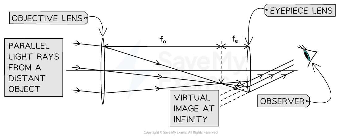
Ray diagram of a refracting telescope in normal adjustment showing axial and non-axial rays
A simple refractor is usually adjusted so that the final image is at infinity
This is known as normal adjustment
For a refractor to be in normal adjustment
Both lenses must be arranged so that their focal points meet in the same place
The focal length of the objective lens must be longer than the focal length of the eyepiece lens, i.e.
Note: in the exam, you will be expected to draw this ray diagram with at least 3 non-axial rays - see the worked example below
Worked Example
Draw a ray diagram for an astronomical refracting telescope in normal adjustment.
Your diagram should show the paths of three non-axial rays passing through both lenses.
Label the principal foci of the two lenses.

Answer:
Step 1: Start by drawing and labelling the two lenses
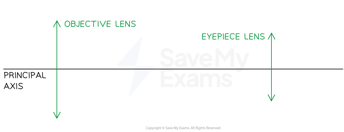
If the question does not include a principal axis, make sure to draw this first!
You can draw the lenses as lines with arrows or very thin ellipses
Step 2: Mark and label the common principal foci
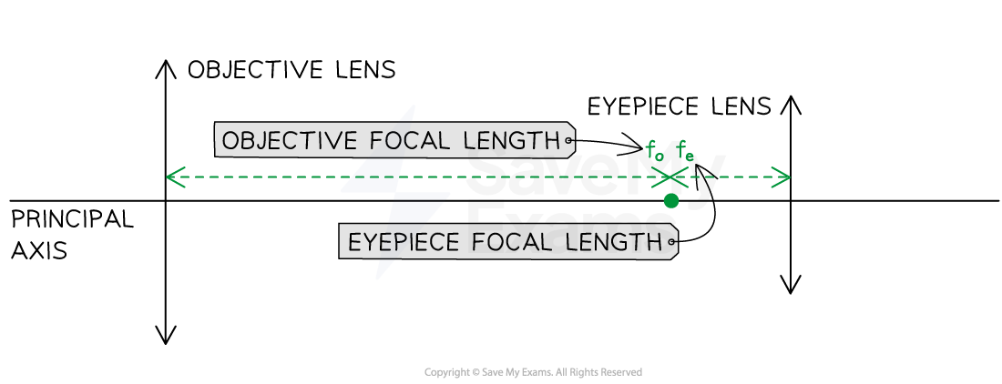
The objective focal length must be longer than the eyepiece focal length
You could also mark a single point and label it F
Step 3: Draw an off-axis ray through the centre of the objective to the eyepiece
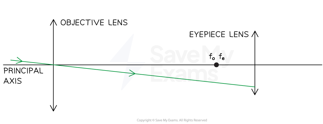
The rays must be off-axis (non-axial), meaning drawn at an angle to the principal axis
Step 4: Draw an arrow to show the intermediate image from the common principal foci to this ray

You don't have to do this step, but it will help the examiner to clearly see your working
Step 5: Draw a construction line from the end of the intermediate image through the centre of the eyepiece

You don't have to do this either, but it will help the examiner to clearly see your working
Step 6: Draw two rays to the eyepiece, crossing at where the focal lengths meet
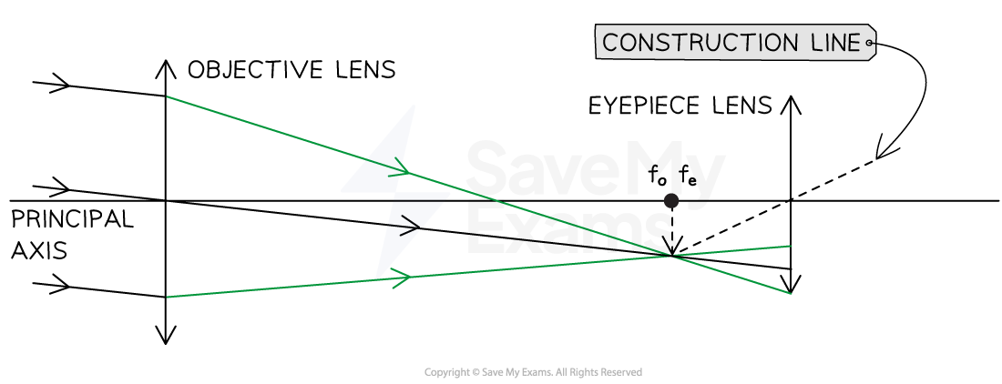
Step 7: Draw the continuation of the three rays from the eyepiece, parallel to the construction line
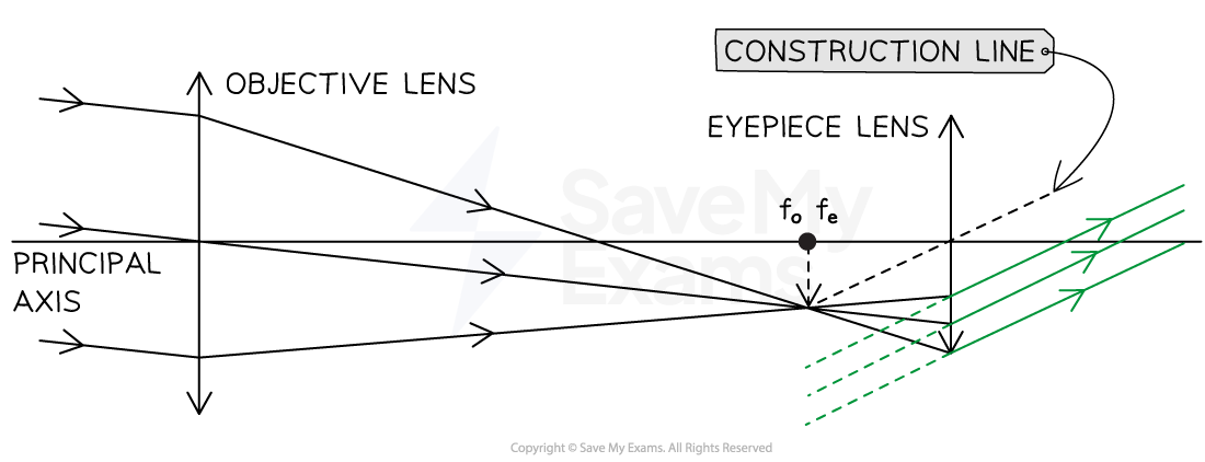
Step 8: Check your final image and make sure everything is included to gain the marks

For a three-mark question, examiners will be looking for:
Both focal points are marked and labelled at the same point on the principal axis with
Three off-axis rays drawn through the objective lens
Three rays drawn through the eyepiece lens parallel to a construction line
Examiner Tips and Tricks
It is important that you get lots of practice drawing this diagram, it's a common exam question, and examiners can be extremely meticulous when it comes to marking them
Make sure to avoid these common problems when drawing the diagram:
Drawing axial rays (parallel to the principal axis) rather than non-axial rays (at an angle to the principal axis)
Bending the central ray at the objective lens
Bending the rays at the intermediate image (i.e. at
,
)
Not drawing the rays parallel to each other, or the construction line, at the eyepiece lens
Labelling the principal foci where the rays cross, rather than on the principal axis
Angular Magnification
The angle, in radians, subtended by an object of height
, at a distance
away is given by:
This is also known as the angular size of an object
Note: this is the angle between the rays seen at the extremities of the object to the eyes or telescope lens
Angular Size of the Moon
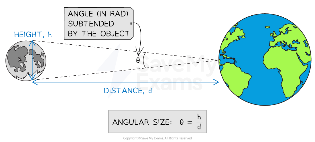
How to calculate the angle subtended by an astronomical object
For astronomical objects that are very distant, essentially at infinity, it isn't easy to directly measure their size or the distance to them
Therefore, it makes more sense to use angular magnification, which is defined as:
Like magnification, angular magnification is a ratio and has no units
Angles Subtended by the Object & the Image
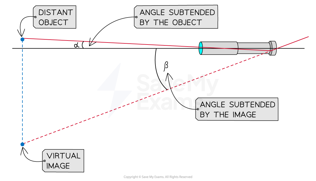
The angle subtended by an astronomical object and the angle subtended by the image produced by the telescope
Telescopes magnify the angular size of distant objects, this means that:
The telescope produces an image which subtends a larger angle than the object
When viewed by the naked eye, the angle subtended by the object
is much less than the angle subtended by the image
when viewed through a telescope
Angular Magnification of a Refractor
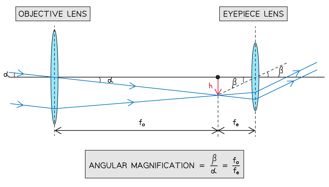
How to determine the angular magnification of a refracting telescope in normal adjustment
When looking at the ray diagram of a refractor in normal adjustment, the rays of light inside the telescope can be seen to form similar triangles
The angle subtended by the object
can be described as:
The angle subtended by the image
can be described as:
Where:
= the height of the image (m)
= focal length of the objective lens (m)
= focal length of the eyepiece lens (m)
when the angle is very small (rad)
Combining these equations leads to the following expression for angular magnification:
This equation tells us that to achieve greater magnifications:
longer objective focal lengths
and shorter eyepiece focal lengths
are required
refractors must be very long, as the length is equal to
Worked Example
A student is looking for suitable lenses to use in a simple refracting astronomical telescope.
The student sets out to measure the focal length of a converging lens by placing an object and screen at a fixed distance of 300 cm apart.
A sharp image is observed on the screen when the lens is placed between the object and the screen at a distance of 207 cm from the object.
(a) Calculate the focal length of the lens.
(b) State whether the lens formed the eyepiece or objective, giving reasons for your answer.
Answer:
Part (a)
Step 1: Sketch a quick diagram to visualise the scenario
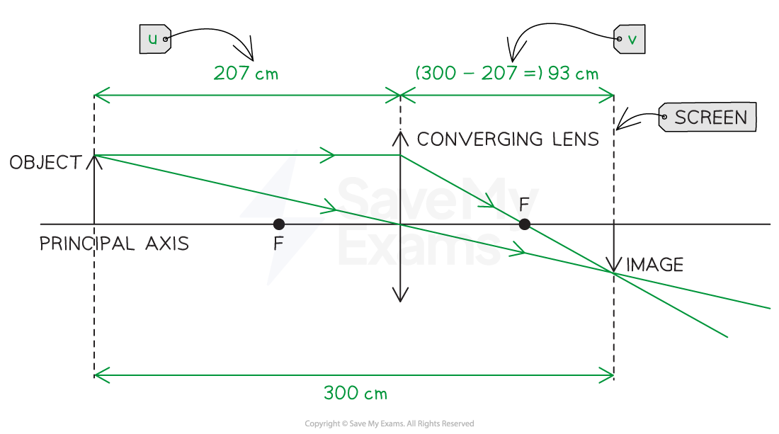
Step 2: Write down the lens equation
lens equation:
Where u = 207 cm and v = 93 cm
Step 3: Calculate the focal length of the lens
Part (b)
You could either argue...
The eyepiece forms a virtual, inverted, magnified image
The objective lens forms a real, inverted, diminished image of a distant object very near the focal point of the eyepiece
The image formed by the lens in (a) is real, inverted, and diminished
Therefore, the lens must be an objective lens
Or, you could argue...
In a refracting telescope, angular magnification is given by:
Hence, the eyepiece must have a shorter focal length and the objective must have a longer focal length:
For the best possible magnification, the image due to the objective lens, which acts as the object for the eyepiece lens, must be located at the focal point of the eyepiece
Hence, the two lenses must be separated by a distance
(i.e. the telescope length)
Therefore, the lens must be an objective lens
Worked Example
An astronomical refracting telescope which is 1.23 m long and has an angular magnification of 200 is used to observe Neptune at its closest approach to Earth.
distance from Earth to Neptune at closest approach = 4.3 × 10⁹ km
diameter of Neptune = 4.9 × 10⁴ km
(a) Calculate the focal lengths of the objective lens and eyepiece lens.
(b) Calculate the angle subtended by the image of Neptune when viewed through this telescope.
Answer:
Part (a)
Step 1: List the relevant equations and known quantities
Telescope length:
Angular magnification:
Step 2: Write an expression for one of the focal lengths in terms of the other
Step 3: Solve to determine the focal lengths of the lens
Focal length of the eyepiece:
Focal length of the objective:
Part (b)
Step 1: Recall the equations for angular size and angular magnification
Angular size:
Where diameter, h = 4.9 × 10⁴ km and distance, d = 4.3 × 10⁹ km
Angular magnification:
Where α = angle subtended by Neptune at unaided eye and β = angle subtended by the image of Neptune at eye
Step 2: Determine the angle subtended by Neptune at unaided eye
The angle subtended by Neptune with the unaided eye: α = 1.14 × 10⁻⁵ rad
Step 3: Determine the angle subtended by the image of Neptune at the eyepiece
Angle subtended by the image of Neptune at eyepiece: β = 2.28 × 10⁻³ rad

Unlock more, it's free!
Did this page help you?