Lenses & Ray Diagrams for Telescopes (AQA A Level Physics): Revision Note
Exam code: 7408
Lenses & Ray Diagrams for Telescopes
A lens is a piece of equipment that forms an image by refracting light
There are two types of lenses:
A convex, or converging lens
A concave, or diverging lens
Note: in the Astrophysics module, only converging lenses will be discussed
In a converging lens, parallel rays of light are brought to a focus along the principal axis
This point is called the focal point
The distance from the centre of the lens to the focal point is called the focal length
This length depends on how curved, or how thick, the lens is
The more curved (thicker) the lens, the shorter the focal length
The shorter the focal length, the more powerful the lens

The focal length is shorter in a lens that is thicker and more curved. This makes for a more powerful lens
Real & Virtual Images
Images produced by lenses can be either real or virtual
Real image | Virtual image |
|---|---|
light converges towards a focal point | light diverges away from a focal point |
always inverted | always upright |
can be projected onto a screen | cannot be projected onto a screen |
intersection of two solid lines | intersection of two dashed lines (or a dashed and a solid line) |
 example: image from a projector onto a screen |  example: image in a mirror |
Constructing Ray Diagrams
When constructing ray diagrams of refractors, it is generally assumed that the lenses used are very thin
This simplifies the situation by reducing the amount the incident rays of light refract
As a result, the three main rules for constructing ray diagrams are as follows:
1. Rays passing through the principal axis will pass through the optical centre of the lens undeviated

2. Rays that are parallel to the principal axis will be refracted and pass through the focal point f

3. Rays passing through the focal point f will emerge parallel to the principal axis

Image Formation by a Converging Lens
Images formed by lenses can be described by their
Nature: Real or virtual
Orientation: Inverted or upright (compared to the object)
Size: Magnified (larger), diminished (smaller), or the same size (compared to the object)
Drawing ray diagrams of real images
For an object placed at a distance greater than 2 focal lengths...

The image that forms will have the following properties:
The image forms... | between f and 2f |
The nature of the image is... | real |
The orientation of the image is... | inverted |
The size of the image is... | diminished |
For an object placed at a distance equal to 2 focal lengths...

The image that forms will have the following properties:
The image forms... | at 2f |
The nature of the image is... | real |
The orientation of the image is... | inverted |
The size of the image is... | the same |
For an object placed at a distance between 1 and 2 focal lengths

The image that forms will have the following properties:
The image forms... | beyond 2f |
The nature of the image is... | real |
The orientation of the image is... | inverted |
The size of the image is... | magnified |
Drawing ray diagrams of virtual images
For an object placed at a distance less than the focal length (i.e. a magnifying glass):

The image that forms will have the following properties:
The image forms... | at 2f (on the same side as the object) |
The nature of the image is... | virtual |
The orientation of the image is... | upright |
The size of the image is... | magnified |
Worked Example
Draw a ray diagram to show how a converging lens can be used to form a diminished image of a real object.
Label the object, image and principal foci of the lens on your diagram.
Answer:
Step 1: Start by drawing and labelling a principal axis and the lens as a line or a very thin ellipse

Step 2: Mark and label the focal points on each side of the lens

Step 3: Draw and label the object at a distance greater than the focal length on the left side of the lens

Tip: the object should be placed a distance of at least 2F away from the lens
Step 4: Draw a ray through the optical centre of the lens

Step 5: Draw a second ray from the object to the lens which is parallel to the principal axis

Step 6: Draw the continuation of the ray passing through the focal point on the right side of the lens

Step 7: Draw and label the image at the point where the rays meet

Step 8: Check your final image and make sure everything is included to gain the marks

For a three-mark question, examiners will be looking for:
One ray drawn through the optical centre of the lens
A second ray drawn which produces a diminished (smaller) image (which must pass through a labelled focal point)
Both the object and the image must be drawn and labelled correctly
Examiner Tips and Tricks
When drawing ray diagrams, convex (converging) and concave (diverging) lenses can be simplified using the following symbols:

The Lens Equation & Magnification
The Lens Equation
The lens equation relates the focal length of a lens to the distances between the lens and the image and the object
Where:
f = focal length (m)
v = distance of the image from lens (m)
u = distance of the object from lens (m)
Lens Equation for a Real Image

All values are positive for a real image
This equation only works for thin converging (or diverging) lenses
If the image is real, the value of v is positive
If the image is virtual, the value of v is negative
Lens Equation for a Virtual Image

A virtual image forms on the same side as the object making the value of v negative
Magnification as a Ratio of Heights
Magnification, M, is the ratio of the image height to the object height
Where:
= magnification
= image height (m)
= object height (m)
Magnification as a Ratio of Distances
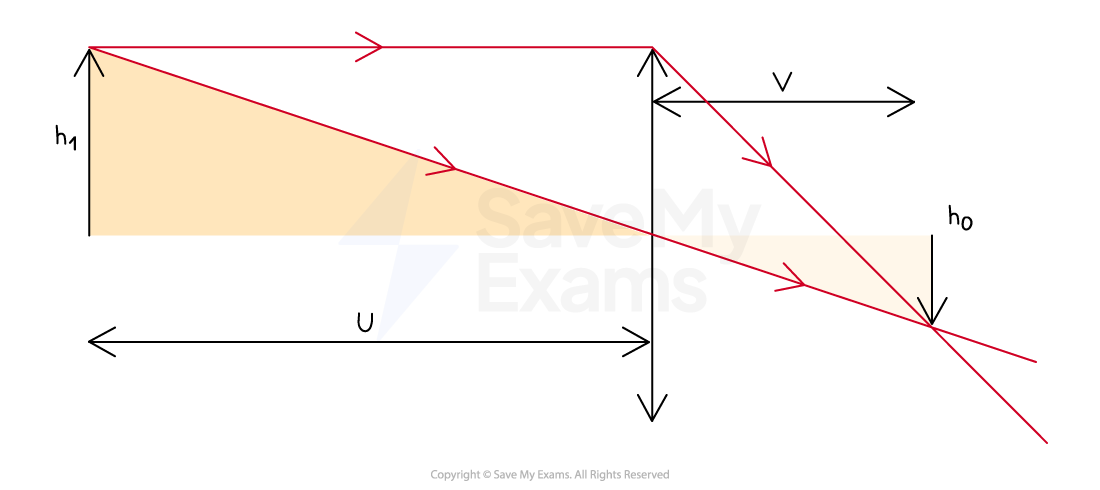
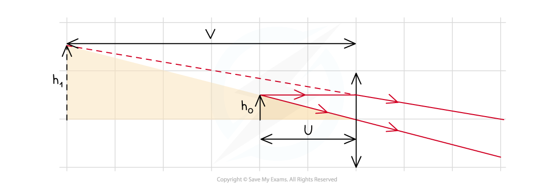
A diagram of an object and its real image will produce similar triangles
Therefore, magnification can be determined by comparing the distances from the lens to the object and the image
Magnification Ray Diagram for a Real Image

Magnification for a real image can be derived using similar triangles
This also works for virtual images
Magnification Ray Diagram for a Virtual Image

Magnification for a virtual image can also be derived using similar triangles
As magnification can be described using the ratio of the two opposite sides
and
, the same ratio must apply to the two adjacent sides
and
Therefore, magnification can also be written as:
Where:
= magnification
= distance from lens to image (m)
= distance from lens to object (m)
Since magnification is a ratio, it has no units
Worked Example
A magnifying glass has a focal length of 15 cm. It is held 5 cm away from a component which is being examined.
Determine the magnification of the image.
Answer:
Step 1: Write the known values
Focal length, f = 15 cm
Distance between object and lens, u = 5 cm
Step 2: Use the lens formula and rearrange to make v the subject
The negative sign indicates a virtual image is formed (expected for a magnifying glass) and can be ignored for the next step
Step 3: Use the magnification formula to find the magnification of the image
Examiner Tips and Tricks
Some of the equations on this page may seem different from the equations on the specification for the Astrophysics module - don't worry, these are covered in the next revision note. These notes are here if you need to refresh your knowledge of lenses and ray diagrams from GCSE.

Unlock more, it's free!
Was this revision note helpful?
