Required Practical: Investigating Flux Linkage on a Search Coil (AQA A Level Physics): Revision Note
Exam code: 7408
Required Practical: Investigating Flux Linkage on a Search Coil
Aims of the Experiment
The overall aim of this experiment is to determine how the magnetic flux linkage varies with the angle of rotation of a search coil
This is done by rotating a search coil through a uniform magnetic field created by a larger coil and recording the induced e.m.f within it
This is just one example of how this required practical might be carried out
Variables
Independent variable = Angle between the normal to the search coil and the magnetic field lines, θ
Dependent variable= Induced e.m.f, ε
Control variables:
Area of the search coil, A
Number of loops on both coils, N
Magnetic field strength, B
Frequency of the power supply, f
Equipment List
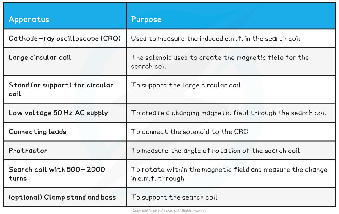
Resolution of measuring equipment:
Protractor = 1º
CRO = 2 mV / div
Method
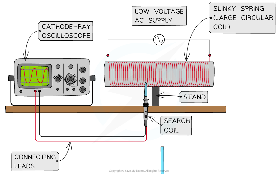
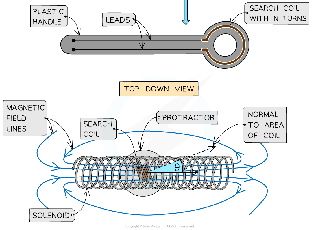
Arrange the apparatus as shown in the diagram above. The slinky spring should be connected to the alternating power supply so the flux through the search coil placed within it will be constantly changing
Set up the CRO so its time-base is switched off, so it only shows the amplitude of the e.m.f. Adjust the voltage per division till the signal can be seen fully on the screen (eg. 10 mV / div)
Position the search coil so that it is halfway along the slinky spring
Orient the search coil so it is parallel to the slinky spring (and the plane of its area is perpendicular to the field)
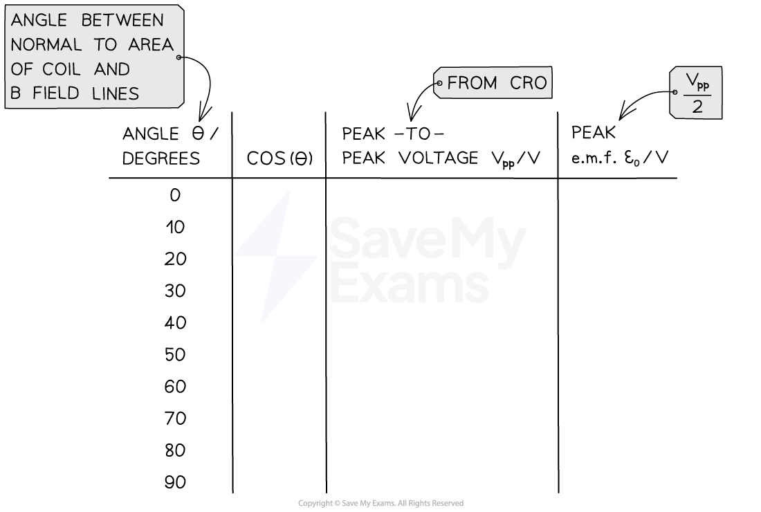
Record the induced e.m.f in the search coil from the amplitude of the CRO trace. This should ideally be the peak-to-peak voltage (Vpp) which will then be halved for the peak e.m.f ε0
Rotate the search coil by 10º (in either direction) using the protractor
Record the new Vpp and repeat the procedure until the search coil is at 90º to the slinky spring
An example table might look like this:
Analysing the Results
The e.m.f induced in the search coil is given by the expression:
This is obtained through the following logic:
If a constant uniform magnetic field was used in this experiment, with a DC source, the flux linkage through the search coil would be given by the equation:
The magnetic field, however, is alternating with angular frequency ω
This is a result of the AC source used that oscillates with frequency f
Where ω = 2πf
As a result of this, the flux linkage through the coil oscillates at the same frequency as the AC source,
Current through the coil is given by:
for peak current
So, magnetic flux density is proportional to current and is given by:
for peak magnetic flux density
Hence,
To find the peak induced e.m.f in the search coil, apply Faraday's law (this is really just differentiating the above expression with respect to time):
The expression for peak e.m.f, ε0 , from the above equation is found when sin(ωt) is 1 or −1:
Recall that we are able to measure ε0 by halving the peak-to-peak voltage on the CRO
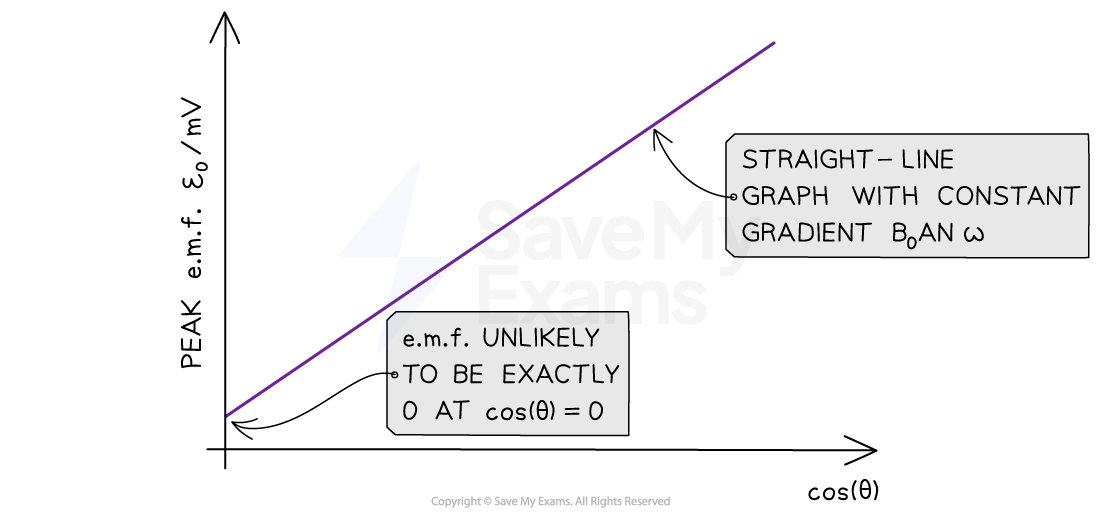
Compare this to the straight-line equation: y = mx + c
y = ε0
m = B0ANω
x = cos(θ )
c = 0
Plot a graph of peak e.m.f ε0 against cos(θ ) and draw a line of best fit
This should be a straight-line graph
This shows that the induced e.m.f in the search coil is proportional to the cosine of the angle between the search coil and the direction of the magnetic field lines
Evaluating the Experiment
Systematic Errors:
Reduce systematic errors by calibrating the search coil using a known magnetic field and oscilloscope
The field lines are unlikely to be perfectly parallel and perpendicular to the area of the coil
Therefore, the graph is likely to have a y-intercept for cos(θ ) = 0
Read the angle from the protractor far above and from the same point every time to reduce parallax error
Random Errors:
The experiment could be made more reliable by repeating for a full turn (θ = 360°)
An improvement could be to use a calibrated motor to rotate the search coil by fixed increments
Use blu-tack to make sure the protractor stays in the same place for each reading
Safety Considerations
Keep water or any fluids away from the electrical equipment
Make sure no wires or connections are damaged and contain appropriate fuses to avoid a short circuit or a fire
Don't exceed the specified current rating for the coil in order not to damage it
The larger coil will heat up whilst the current is through it, especially if it is very thin
Therefore, make sure not to leave the current on for longer than necessary

Unlock more, it's free!
Did this page help you?